5 Commissioning
Linear actuators MC160 • MC161 • MC163
24 Version 2.1 - March 2011 Operating Manual
5 Commissioning
Risk of injury from electric shock by live parts!
When the power supply is on there is a danger of electric shock due to live parts.
• Prior to commencing any work, ensure that the actuator is safely disconnected
from the power supply system.
• Secure against unauthorised restarting.
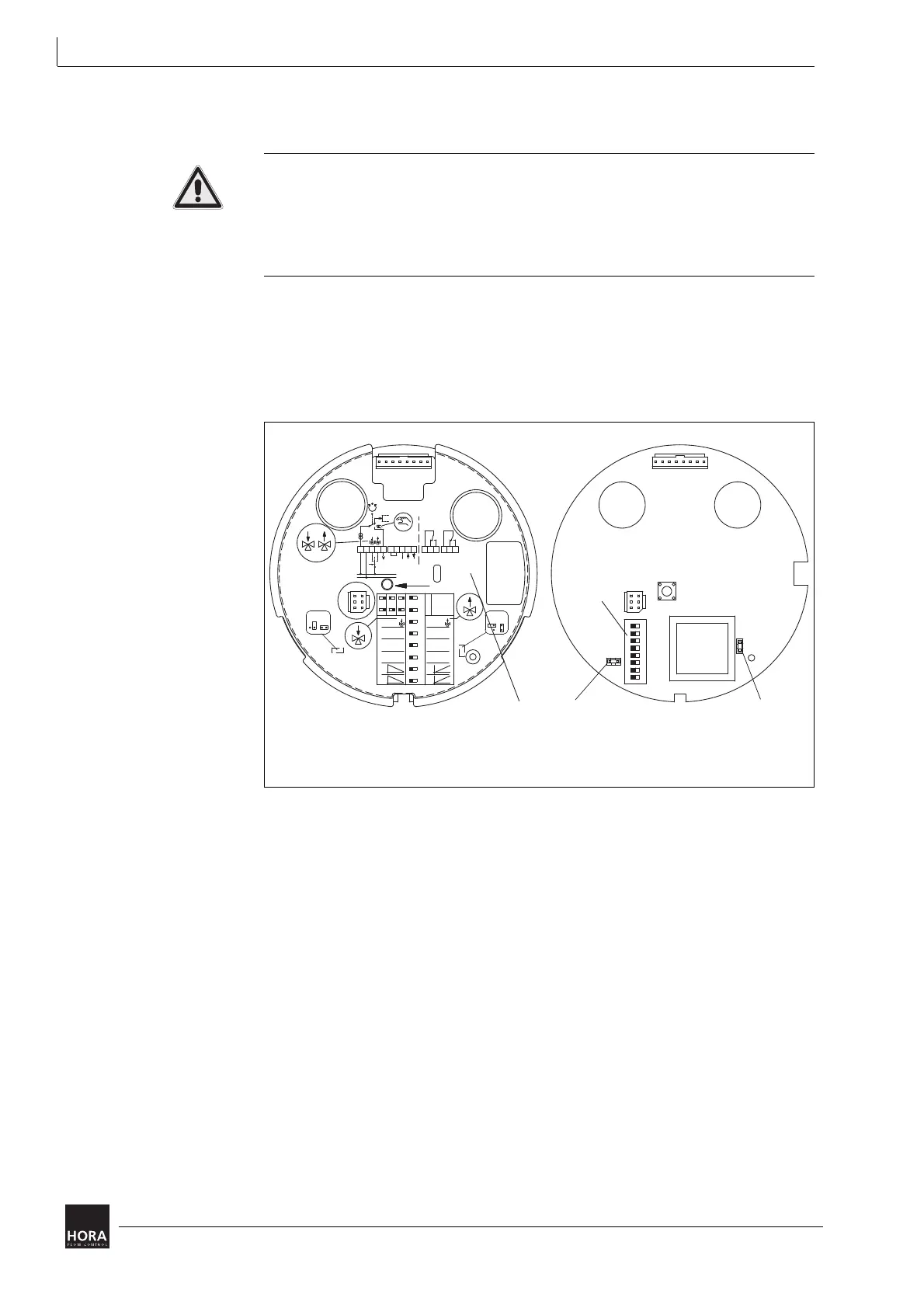
Operating parameters are set at the encoding switches (116) and jumpers. The
encoding switches and jumpers are situated underneath the PCB cover (33) in
the actuator housing (1).
4.4 Assembling/disassembling the cover on page 16
4.5.2 Removing the PCB cover on page 20
33 PCB cover 116 Coding switch
JP1 Jumper
JP2 Jumper
diagram 17 PCB cover, encoding switch and jumper
87654321
LED
116
on
x
y
0,5
0,3
0...10 V
(0...20 mA)
ausein
12345678
x
2...10 V
(4...20 mA)
Stellzeit
6 s/mm
Pause
Autotest
Endpos.
y
Stellzeit
4 s/mm
Pause
Autotest
Endpos.
0,05
0,15
ON
Hysterese
V
R= return signal
S
INIT
20 21 22 23 24 25
WE1 WE2
GND
230 VAC;
24 VAC;
24 VDC
N (GND)
U
T
XY
N2B2B1
R32
N1
UB
V
mA
JP2
JP1
1600 N
1000 N
33


 To Next Page