4 Assembly
Linear actuators MC100 • MC103
Operating Manual Version 2.1 - March 2011 17
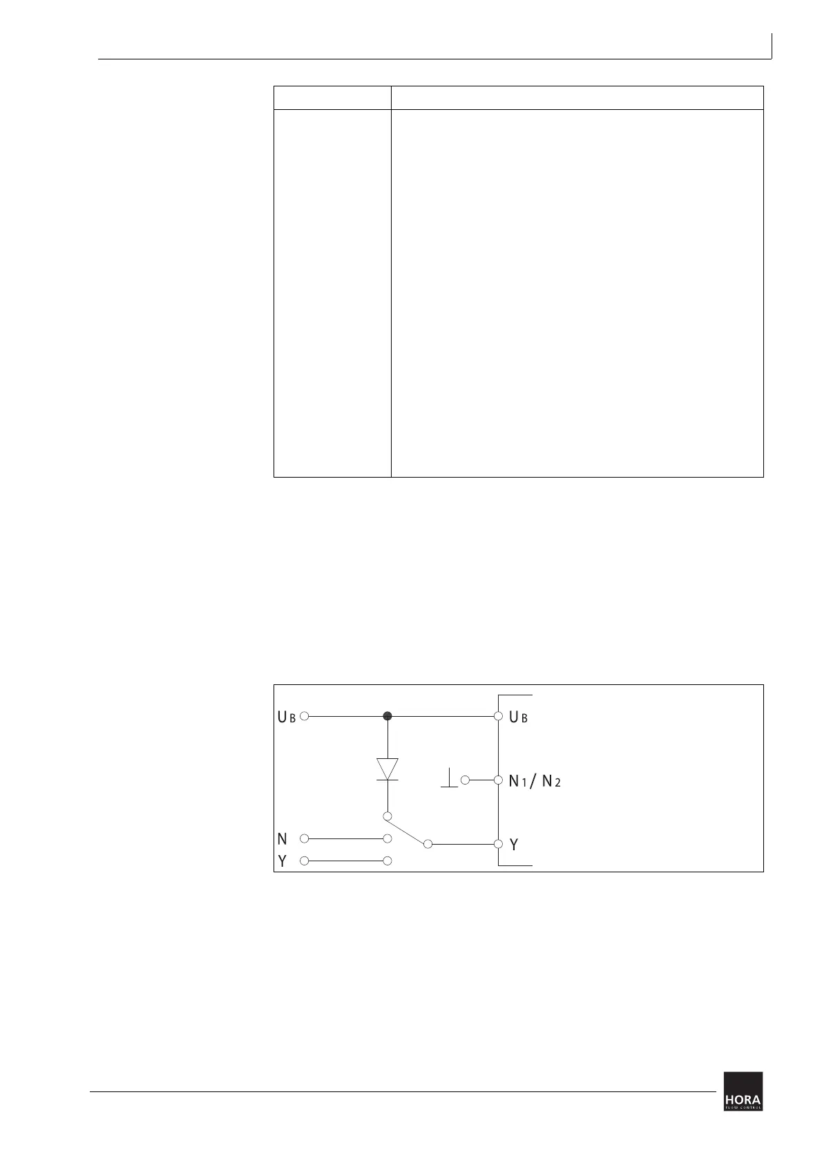
4.5.1 Controller independent circuit
When working with 24 V supply voltage and 0 … 10 V DC / 2 … 10 V DC input
signal you can switch the actuator controller-independently via a three-step
toggle switch in the control cabinet.
How to switch the actuator controller-independently
1 Run the supply voltage 24 V AC via a diode and a three-step toggle switch to
terminal Y.
2 Using the toggle you can move the linear actuator to the following positions:
• Closed-loop control by input signal Y (normal operation)
• 10 V-position
• 0 V-Position, the linear actuator can be moved to the position selected by
encoding switch S6 at 2 … 10 V DC.
5.1 Operating parameters and encoding switch settings on page 23
5.7 Setting the limit position on page 25
Terminal Description
UB, N1 Supply voltage:
2 Control voltage for downward movement during three-point mode
3 Control voltage for upward movement during three-point mode
R Response signal during “manual” mode
• R= 24 V DC max. 35 mA
B1, B2 Binary input / frost protection function
N2 Zero potential of signals X, Y and R
• When the zero potentials of signals X, Y and R are identical to
the zero potential of the supply voltage it is possible to bridge
terminals N1 and N2.
• If you run the actuator in continuous mode at 230 V you will
have to connect N2.
• If you run the actuator in three-point mode at 230 V you will
have to connect N2 if you wish to use X or R at the same time.
Y Input signal continuous mode
X Output signal continuous mode
20, 21, 22 Terminals path switch unit PS1
23, 24, 25 Terminals path switch unit PS2
table 3 Key to wiring diagram
z
diagram 9 Controller independent circuit
Example: 1N4001;
1N4148
10 V Pos.
0 V Pos.
Closed-loop control