4 Assembly
Linear actuators MC100 • MC103
14 Version 2.1 - March 2011 Operating Manual
How to assemble linear actuator type MC103:
1 Insert the C-frame (28).
diagram 6 on page 13
2 Pull the adapter (3) off the clutch (6).
3 Screw the hexagon locknut M10 (451) spanner width 17 onto the valve stem
(18).
4 Screw the adapter (3) onto the valve stem (18).
5 Fix the valve stem (18) by the hexagon locknut (451), in order to prevent
skewing.
6 Fit the spacer (51) on the valve neck (19).
7 Fit the actuator and crossbeam (2) and hexagon nut (459) on the valve neck
(19).
8 Insert the C-frame (28) and pull the valve stem upwards (18) until the valve stem
locks (18) into the clutch (6).
9 Fix the crossbeam (2) using a hexagon nut (459) spanner width 50.
How to disassemble the linear actuator
1 Follow the sequence of operation in reverse order.
4.4 Assembling/disassembling the cover
The cover contains the terminals for electric connection.
Risk of injury from electric shock by live parts!
When the power supply is on there is a danger of electric shock due to live parts.
• Prior to commencing any work, ensure that the actuator is safely disconnected
from the power supply system.
• Secure against unauthorised restarting.
• Remove the cover only momentarily.
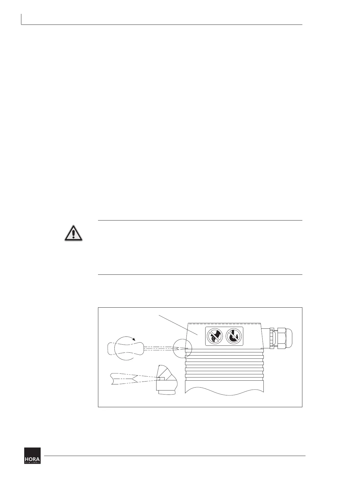
How to remove the cover
1 Insert a screwdriver in the notch of the cover and lift the cover (201).
201 Cover
diagram 7 Removing the cover