5 Commissioning
Linear actuators MC250 • MC253 • MC500 • MC503
Operating Manual Version 2.1 - March 2011 23
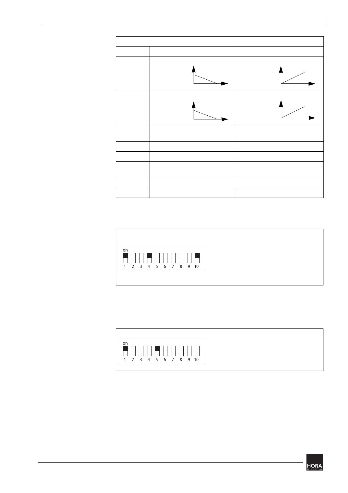
5.2 Set input signal
Further information: Input signal (Y) on page 8
5.3 Set actuating time
Further information: 2.4.5 Set time on page 9
Switch on off
S1 Ready for operation -
S2 X characteristic
curve
X characteristic
curve
S3 Y characteristic
curve
Y characteristic
curve
S4 Input signal (Y)
0 … 10 V DC or 0 … 20 mA
Input signal (Y)
2…10VDC or 4…20mA
S5
A
ctuating time 3.5 s/mm Actuating time 5 s/mm
S6 Autotest and Autopause on Autotest and Autopause off
S7 Limit position for actuator spindle
extended
Limit position for actuator spindle
retracted
S8, S9 The hysteresis (0.05 … 0.5 V) is set using S8 and S9.
S10 Input signal (Y) in mA Input signal (Y) in V
Table 4 Coding switch positions
Diagram 16 Set input signal
0 ... 10 V
0 ... 20 mA
mA
2 ... 10 V
4 ... 20 mA
V
Diagram 17 Set actuating time
3.5 s/mm