4 Assembly
Linear actuators MC55
Operating Manual Version 3.3 - November 2014 15
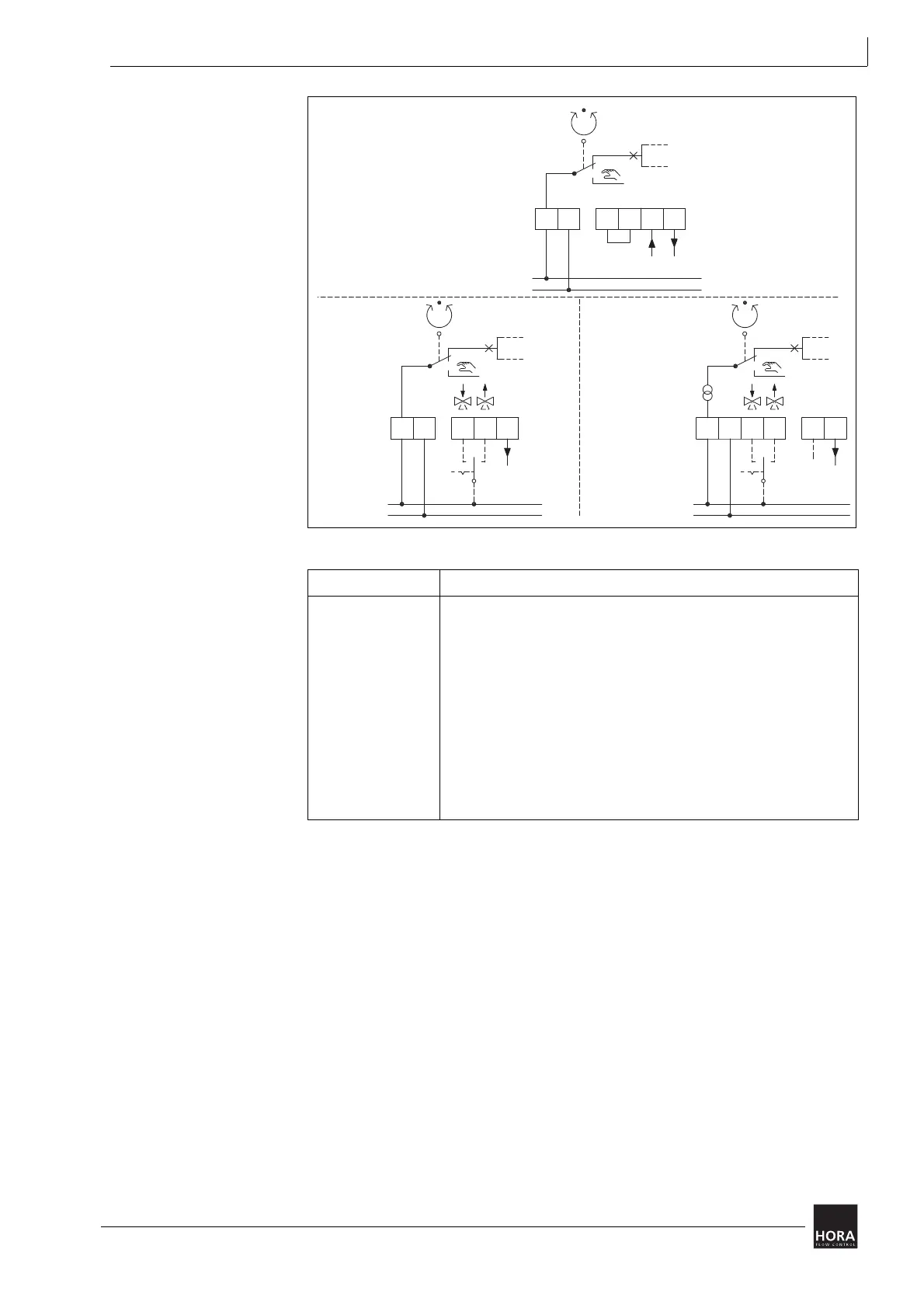
diagram 6 Circuit diagram
Terminal Description
UB, N1 Supply voltage:
2 Control voltage for downward movement during three-point mode
3 Control voltage for upward movement during three-point mode
B1, B2 Binary input / frost protection function
N2 Zero potential of signal X at 230 V AC
• If you run the actuator in three-point mode at 230 V you will
have to connect N2 before you can use X.
Y Input signal continuous mode
X Output signal
table 3 Key to wiring diagram
N (GND)
0
230 VAC
UB N1 N2 X
T
GND
U
32
N (GND)
0
3
N1UB
X
2
24 VAC /
24 VDC
T
U
B1
N (GND)
N1UB XY
24 VAC /
24 VDC
U
B2
 Loading...
