5 Commissioning
Linear actuators MC100 • MC103
26 Version 2.1 - March 2011 Operating Manual
5 Comply with the allowable contact load for the path switch:
6 Disconnect the actuator from the supply and connect the path switch contacts.
7 Close the cover (201) of the linear actuator
How to attach the cover on page 15
105 P1Trim-pot 105 P2Trim-pot
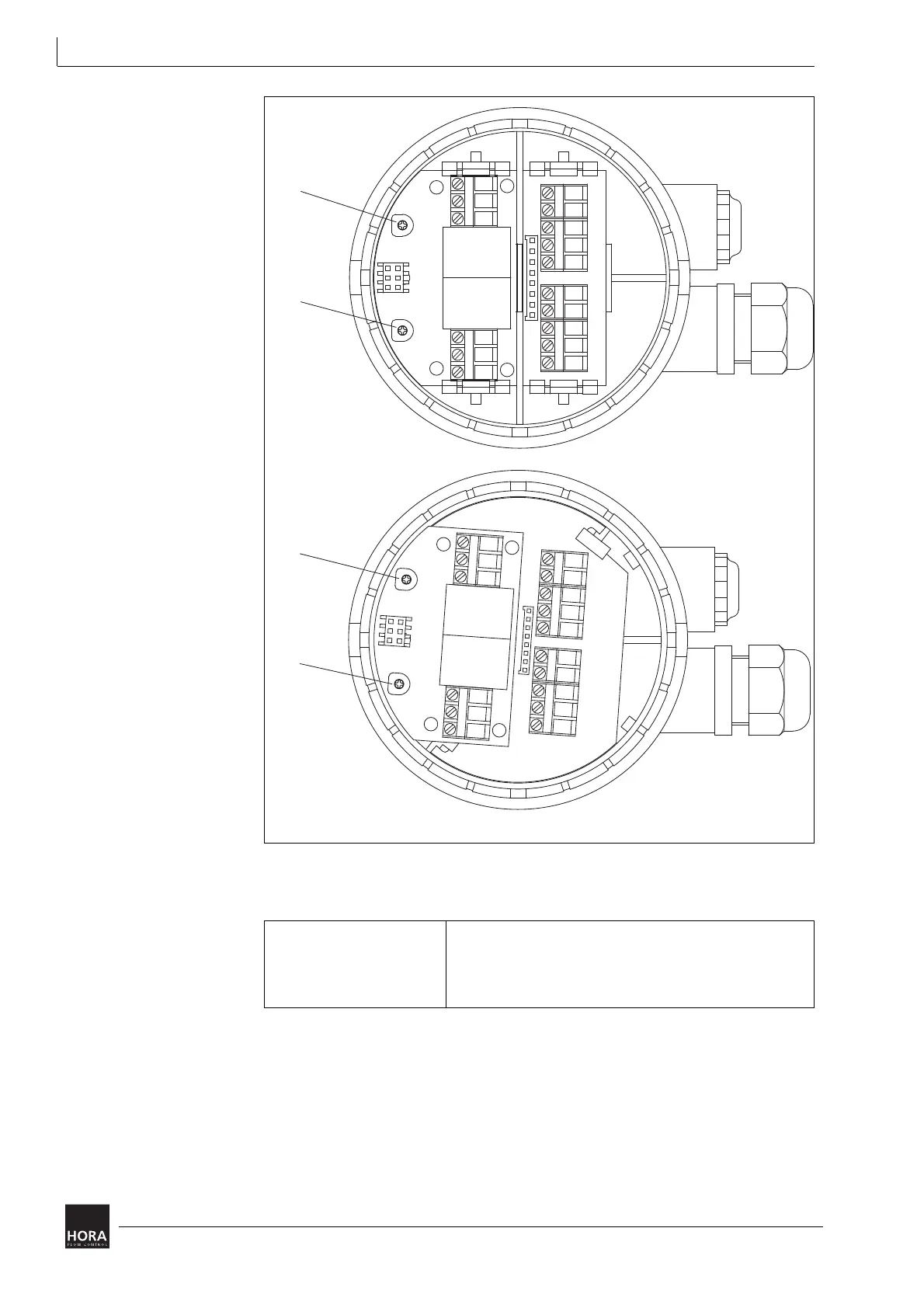
diagram 20 Position switch PCB in cover
105
LED1
LED2
P2
105
P1
LED2
LED1
105
P2
105
P1
24 V
230 V
Nominal load 8 A, 250 V AC
8 A, 30 V DC
Switch voltage max. 400 V AC
max. 125 V DC
table 6 Contact load of path switch
JP2