4 Assembly
Linear actuators MC160 • MC161 • MC163
18 Version 2.1 - March 2011 Operating Manual
How to establish electrical connection
1 Remove the cover (201).
How to remove the cover on page 16
2 Run the cable through the screw joint in the cover to the terminal.
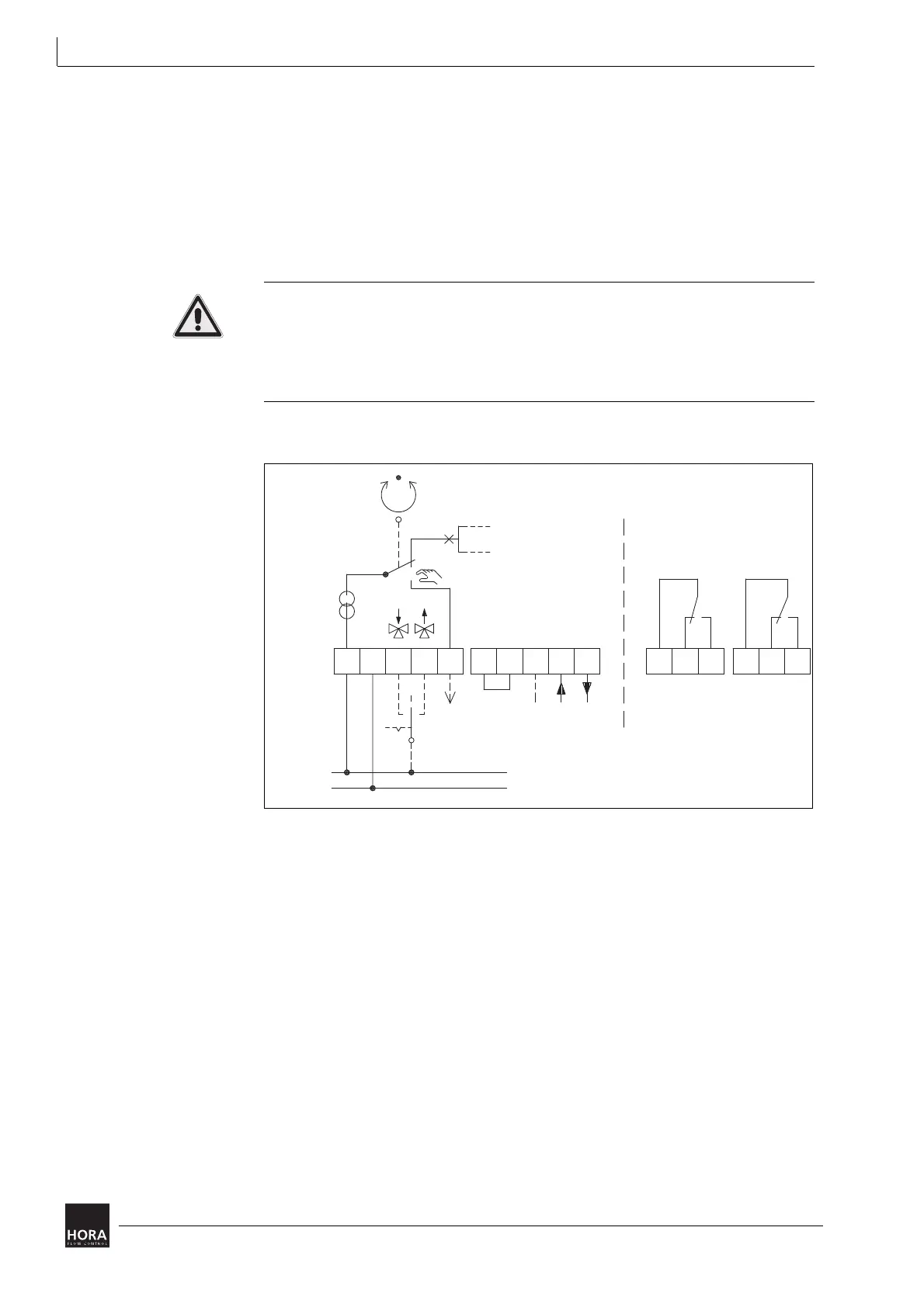
3 Connect the power supply according to the wiring diagram.
diagram 9 on page 18
Hint: The wiring diagram (481) is on the PCB cover(33).
Malfunctions caused by incorrect zero potential!
If the electric power supply for the linear actuator is fed by transducing sensors
with varying zero potentials this may result in incorrect automatic controller action.
• Ensure that the zero potential is properly applied.
table 3 on page 19
4 Tighten the screw joints.
diagram 9 Circuit diagram
24 VDC
24 VAC;
230 VAC;
WE2WE1
N (GND)
GND
T
252423222120XY
N2B2B1
R32
N1UB
U
230 V AC;
24 V AC;
24 V/DC
N (GND)
GND
WE1 WE2