Chapter 1 Getting Started
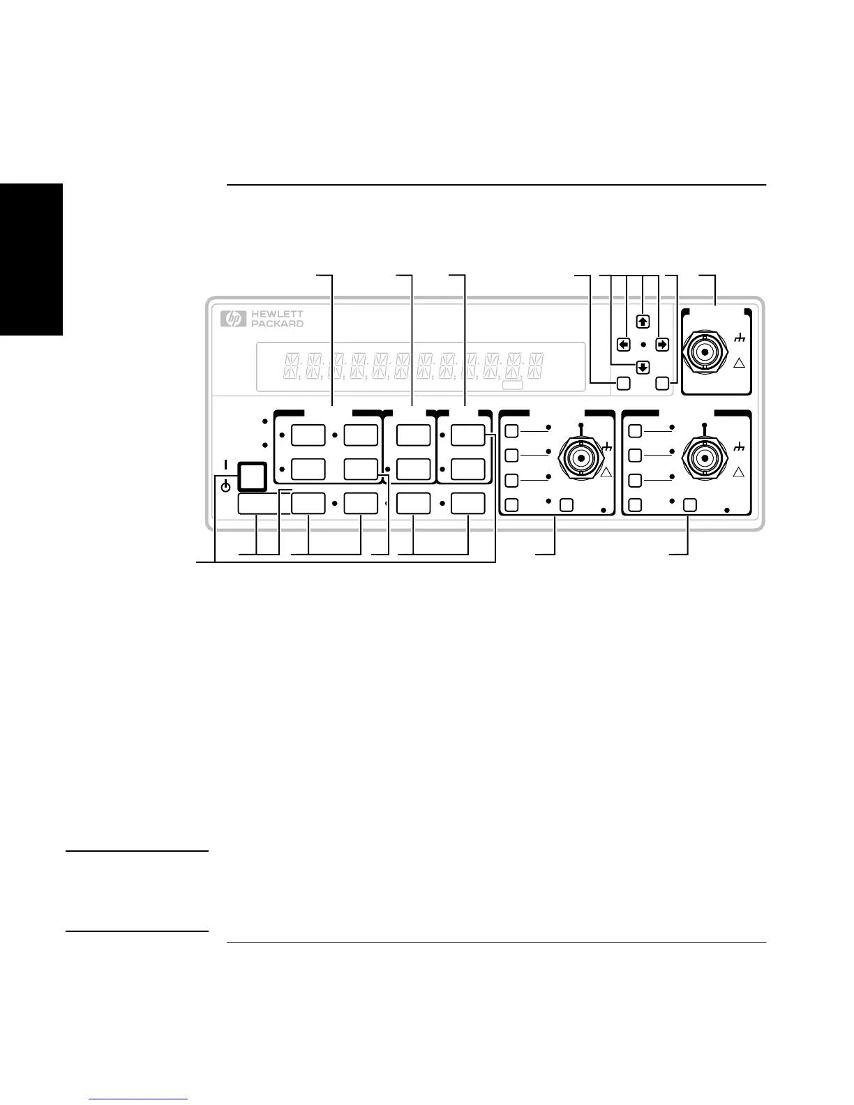
The Front Panel at a Glance
1-2 Operating Guide
1
The Front Panel at a Glance
Note: Unit shown with Option 030.
NOTE
It is normal operation for the fan in the Counter to continue to run after
the Counter is placed in Standby mode. Power to the timebase is
continuous to maintain long term measurement reliability, and the fan
helps maintain timebase temperature stability.
Recall
Utility Menu:
Hold at power up
Save &
Print
Run
LocalUtility
Other
Meas
Limit
Modes
Stats
Time &
Period
Gate &
ExtArm
Uppr &
Lower
Scale &
Offset
Stop/
Single
MEASURE LIMITS MATH CHANNEL 1 CHANNEL 2
CHANNEL 3
Trigger
Sensitivity
X10
Attenuate
100kHz
Filter
Damage Lvl:
5V rms MAX.50Ω
!
Trigger
Sensitivity
X10
Attenuate
100kHz
Filter
Damage Lvl:
5V rms MAX.50Ω
!
Damage Lvl:
5V rms MAX.50Ω
!
100 MHz − 3 GHz
Enter
53131 A
225 MHz
UNIVERSAL COUNTER
+
/
–
Freq &
Ratio
POWER
SRQ
Remote
50Ω
1M Ω
DC
AC
DC
AC
50Ω
1M Ω
23
4
567
1
12 13
9
Period Freq +Wid -Wid Rise Fall Time Ch 1 Ch 2 Ch 3 ExtRef
MHz
µs
Gate
Limit
11
8
10
14
1 Measurement function menu keys
2 Limits menu keys
3 Math menu keys
4 Sign (+ or −) selection toggle key
5 Data Entry/Select (or arrow) keys
6 Enter numeric data (terminate) key
7 3.0/5.0/12.4 GHz RF input channel
(optional)
8 Utility menu key (Hold during
power-up to access Utility functions.)
9 Recall, Save and Print menu keys
10 Gate and External Arm menu key
11 Measurement control keys
12 Channel 1 Trigger/Sensitivity menu
key and input conditioning keys
13 Channel 2 Trigger/Sensitivity menu
key and input conditioning keys
14 Calibration menu key (Hold Scale &
Offset key during power-up to access
Calibration functions.)

 Loading...


