Chapter 1 Getting Started
Making Measurements
Operating Guide 1-15
1
Again, the Counter will automatically display the measured frequency of
the input signal.
If you need or want to change CHANNEL 2’s coupling, impedance, and
triggering conditions to match the input signal you are trying to measure,
the next procedures “To Select Input Coupling and Impedance” and
“To Set Input Channel Trigger Level/Sensitivity” demonstrate this.
Perform these procedures whether or not you want to customize the
Counter’s input conditions to measure your signal; doing this will help you
become familiar with the DC/AC, 50
Ω
/1M
Ω
, and Trigger/Sensitivity
keys.
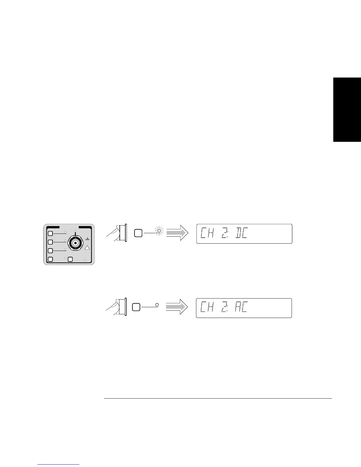
To Select Input Coupling and Impedance
Remember, the input signal is still connected to CHANNEL 2.
Selecting Input Coupling
Channel 2’s input coupling is now set to dc.
If you want to change the coupling back to the default ac coupling, perform
the following step.
CHANNEL 2
Trigger
Sensitivity
DC
AC
50Ω
1M Ω
X10
Attenuate
100kHz
Filter
Damage Lvl:
5V rms MAX. 50Ω
!
DC
AC
DC
AC

 Loading...


