Chapter 1 Getting Started
Making Measurements
1-14 Operating Guide
1
NOTE
Earlier versions of the Counter do not momentarily display the HP-IB
address at turn-on.
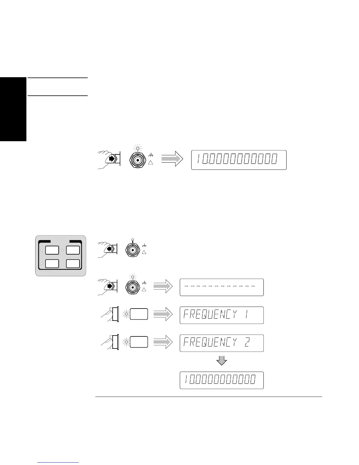
Connect (for demonstration purposes) the Counter’s rear-panel 10 MHz
Out signal to CHANNEL 1 input as shown in the illustrated procedure,
below.
The Counter will automatically display the measured frequency of the
input signal.
Disconnect the demonstration signal from CHANNEL 1, and connect it to
CHANNEL 2 as shown in the following steps.
Freq Ch 1
MHz
Gate
Damage Lvl:
5V rms MAX.50Ω
!
CHANNEL 1
Other
Meas
Time &
Period
Gate &
ExtArm
MEASURE
Freq &
Ratio
Freq &
Ratio
Freq &
Ratio
Freq Ch 1
Freq Ch 1
Freq Ch 2
Freq
MHz
Ch 2
Gate
Damage Lvl:
5V rms MAX.50Ω
!
CHANNEL 2
Damage Lvl:
5V rms MAX.50Ω
!
CHANNEL 1

 Loading...


