Chapter 1 Getting Started
The Display Annunciators at a Glance
Operating Guide 1-9
1
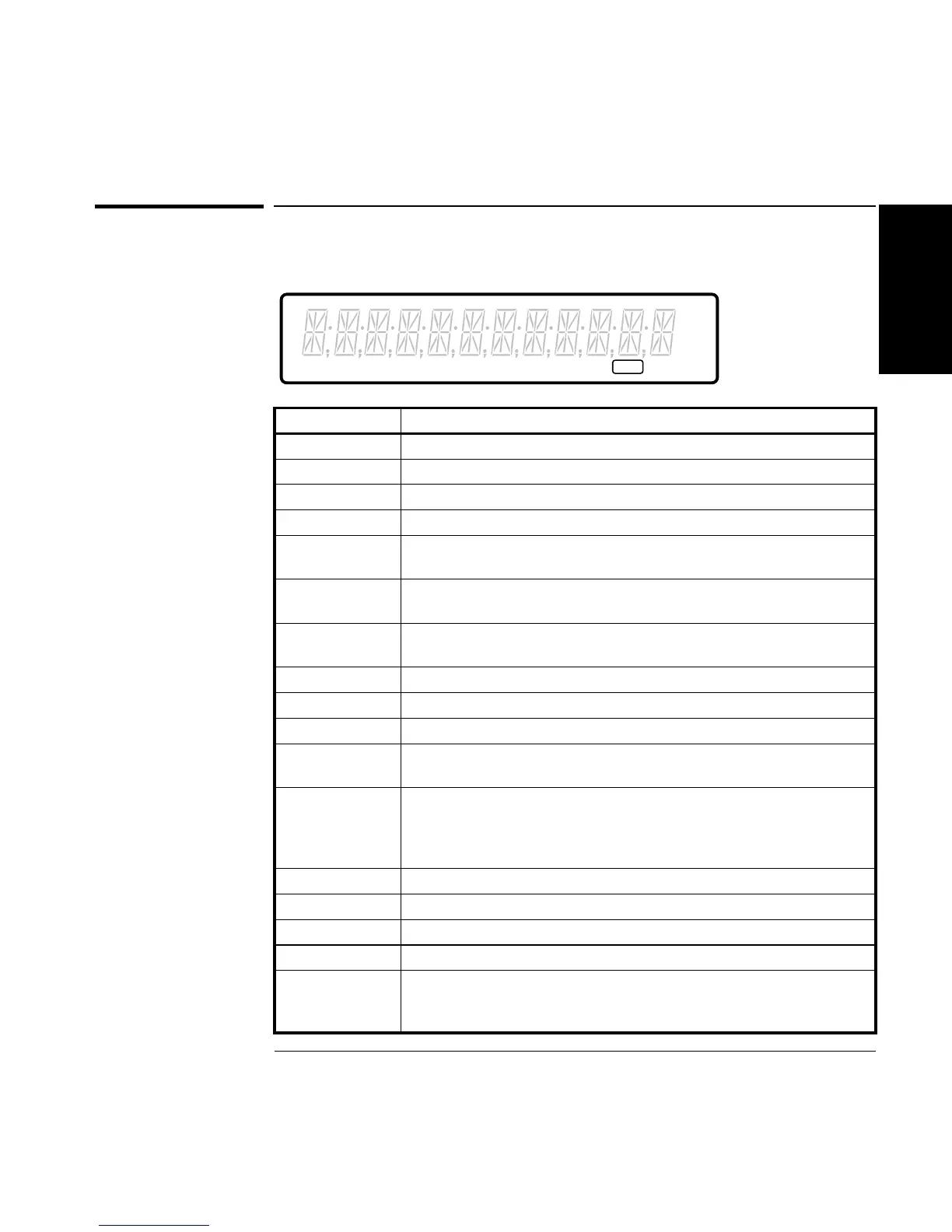
The Display Annunciators at a Glance
Annunciator Indication
Period Counter is set to measure Period.
Freq Counter is set to measure Frequency.
+Wid Counter is set to measure Positive Pulse Width.
−Wid Counter is set to measure Negative Pulse Width.
Rise Counter is set to measure Rise Time. (The Time annunciator is also
turned on when the Rise annunciator is on.)
Fall Counter is set to measure Fall Time. (The Time annunciator is also
turned on when Fall annunciator is on.)
Time Counter is set to measure Time Interval. (The Time annunciator is
also turned on when the Rise or Fall annunciator are on.)
Ch 1 Counter’s channel 1 is selected to measure an input signal.
Ch 2 Counter’s channel 2 is selected to measure an input signal.
Ch 3 Counter’s channel 3 is selected to measure an input signal.
Limit Counter is limit testing and the current measurement exceeds the
user-entered limits.
ExtRef Counter is set to use the signal connected at rear panel Ref In
connector as the timebase (TIMEBAS: EXT); or Counter is set to
automatically (TIMEBAS: AUTO) select the timebase and has chosen
the signal connected at the rear panel Ref In connector.
Hz The displayed data is in units of Hertz.
M The prefix for the units of the displayed data is mega (10
6
).
µ The prefix for the units of the displayed data is micro (10
−6
).
s The displayed data is in units of seconds.
Gate The gate is open. Before a measurement starts, this annunciator is
OFF, indicating the gate is closed. During a measurement, the
annunciator is ON, indicating the gate is open.
Period Freq +Wid -Wid Rise Fall Time Ch 1 Ch 2 Ch 3 Limit ExtRef
MHz
µs
Gate

 Loading...


