Chapter 2 Operating Your Universal Counter
Using the Gate & External Arm Menu Key
2-18 Operating Guide
2
NOTE
When external arming mode is enabled, a signal must be connected to the
Counter’s rear-panel Ext Arm connector.
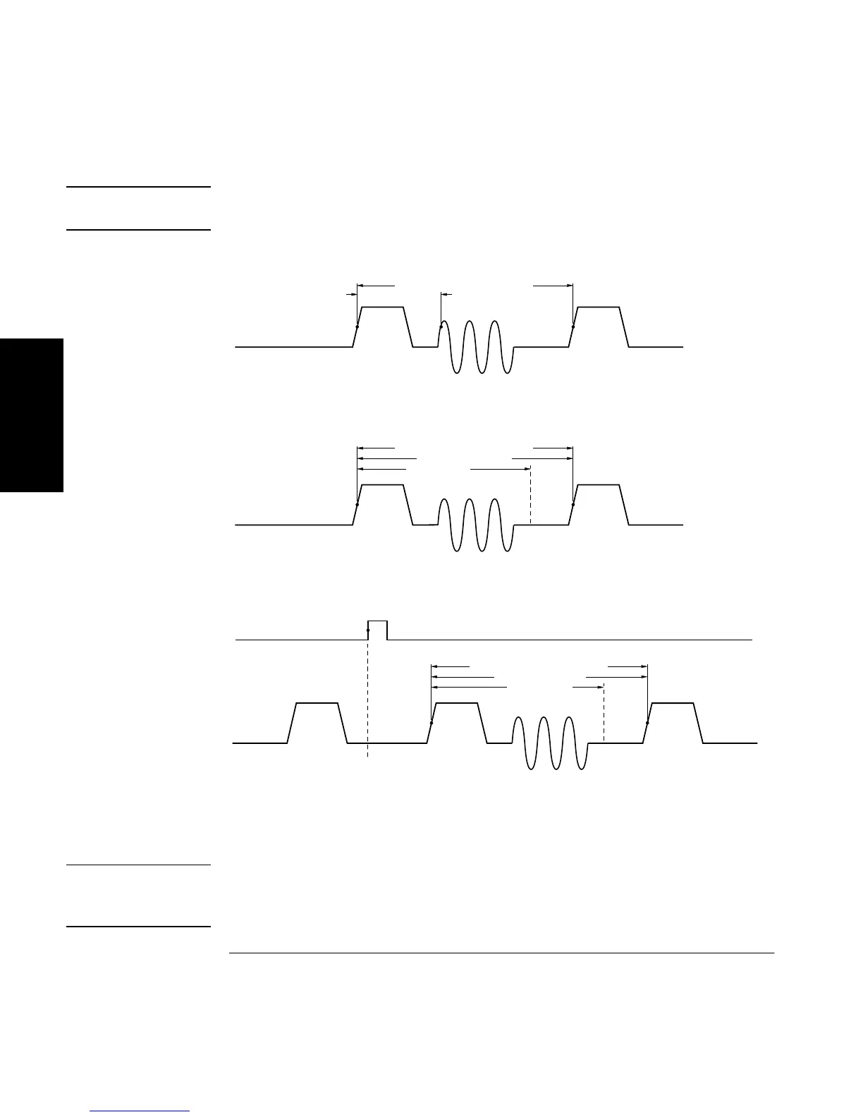
Figure 2-1. HP 53131A (HP 53132A S/N Prefix Below 3646) Time Interval
Delay
NOTE
The examples in Figure 2-1 have the input signal applied to Channel 1
with COMMON 1: ON, Channel 1 SLOPE: POS, and Channel 2 SLOPE:
POS.
DESIRED T.I. MEASUREMENT
START STOP
ACTUAL T.I. MEAS
ARM: AUTO, DELAY: NONE
DESIRED T.I. MEASUREMENT
START STOP
ACTUAL T.I. MEAS
DELAY TIME
ARM: AUTO, DELAY: TIME, TIME: (specified)
(standard T.I. measurement)
DESIRED T.I. MEASUREMENT
START STOP
ACTUAL T.I. MEAS
ARM: EXTERNL, SLOPE: POS, DELAY: TIME, TIME:
specified
DELAY TIME
EXT ARM INPUT

 Loading...


