48
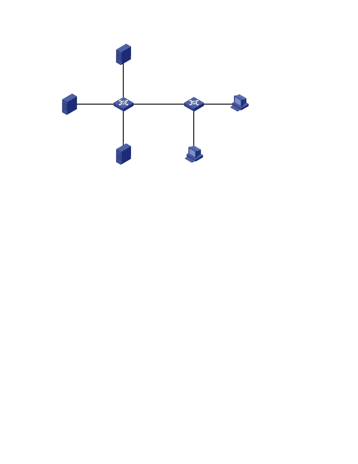
Figure 18 Network diagram for multicast source/user control policy configuration
Switch B
Receiver
Host A
Host B
2.1.1.1/24
GE1/0/2
GE1/0/3
GE1/0/1
Source 2
Source 1
1.1.1.1/24
Switch A
RADIUS server
3.1.1.1/24
GE1/0/1
Vlan-int101
1.1.1.2/24
GE1/0/2
Vlan-int102
2.1.1.2/24
GE1/0/3
Vlan-int103
3.1.1.2/24
GE1/0/4
Vlan-int104
4.1.1.1/24
Configuration procedures
1. Configure IP addresses for interfaces
Configure an IP address and subnet mask for each interface according to Figure 18 (details not shown).
2. Configure Switch A
# Create VLAN 101 through VLAN 104 and assign GigabitEthernet 1/0/1 through GigabitEthernet
1/0/4 to the four VLANs respectively.
<SwitchA> system-view
[SwitchA] vlan 101
[SwitchA-vlan101] port gigabitethernet 1/0/1
[SwitchA-vlan101] quit
[SwitchA] vlan 102
[SwitchA-vlan102] port gigabitethernet 1/0/2
[SwitchA-vlan102] quit
[SwitchA] vlan 103
[SwitchA-vlan103] port gigabitethernet 1/0/3
[SwitchA-vlan103] quit
[SwitchA] vlan 104
[SwitchA-vlan104] port gigabitethernet 1/0/4
[SwitchA-vlan104] quit
# Enable IP multicast routing. Enable PIM-DM on VLAN-interface 101, VLAN-interface 102 and VLAN-
interface 104, and enable IGMP on VLAN-interface 104.
[SwitchA] multicast routing-enable
[SwitchA] interface vlan-interface 101
[SwitchA-Vlan-interface101] pim dm
[SwitchA-Vlan-interface101] quit
[SwitchA] interface vlan-interface 102
[SwitchA-Vlan-interface102] pim dm
[SwitchA-Vlan-interface102] quit

 Loading...


