6. Identify the appropriate screw holes to install the inner rails to your specificdevice:
a. To attach the inner rails to the SAN Switch 2/16, SAN Switch 2/8V , or SAN Switch 2/16V , use
the screw holes marked 8.
b. To attach the inner rails to the SAN Switch 2/32, use the screw holes m arked 32.
c. To attach the inner rails to the 4 /8, 4/16, 8/8, or 8/24 SAN Switches, use the five screw holes
marked 8.Theplenumrequiresonescrewholemarked8 and one screw hole marked 16,as
shown in Figure 15 on page 37.
d. To attach the inner rails to the 4/32, 4/32B, 4/64, 8/40, 8/80 SAN Switch or 400 MP
Router, use the screw holes m arked 16,asshowninFigure 14 on page 36.
e. To attach the inner rails to the MP Router, use the screw holes marked R.
CAUTION:
Remember to use the screw holes labelled 8 when attaching the inner rails to the SAN
Switch 2/16V or SAN Switch 2/16N.
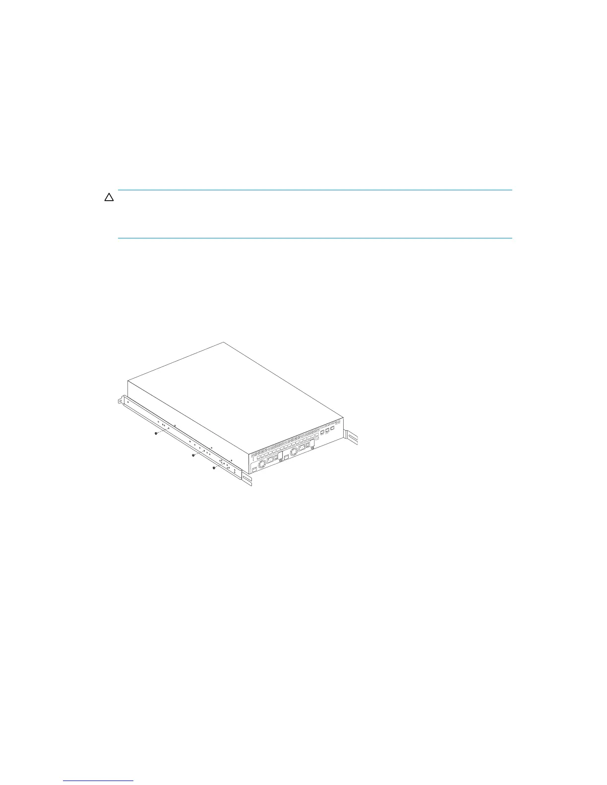
7. Secure the two inner rails (one on each side) to the device, using the appropriate number of
scr ews (see Table 9):
For example, Figure 13 shows an inner rail attached to the MP Router with three screws using the rail
screw holes marked R. Attaching both rails require six screws.
Also, Figure 14 shows an inner rail attached to the 4/64 SAN Switch with five screws using the rail
screw holes marked 16. Attaching both rails require ten screws.
0
SPEED
LINK SPEED
ACTIVITY
MGMT2
MGMT1
CONSOLE
FC/GbE
LINK/ACT
POWER
PORTS
SYSTEM
1
2
3
45
678
9
10
11 12
13
14
15
DC
OK
AC
OK
100-240 V
AC
6.0 A 47-63
Hz
DC
OK
AC
OK
100-240 V
AC
6.0 A 47-63 Hz
Figure 13 Securing the inner rails to an MP Router
8Gb SAN Switch hardware reference manual
35
 Loading...