Installing Field-Replaceable Units (FRUs)
This section lists FRUs and provides installation procedures.
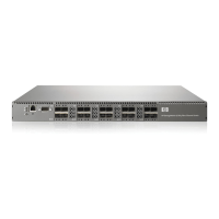
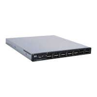
8/8SANSwitchand8/24SANSwitchFRUunits
No components in the 8/8 SAN Switch and 8/24 SAN Switch are field replaceable. If the switch
becomes inoperable, replace the entire switch.
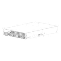
8/40 SAN Switch and 8/80 SAN Switch FRU units
Replace the following FRUs as required.
• Power supp
ly assembly
• Fan assembly
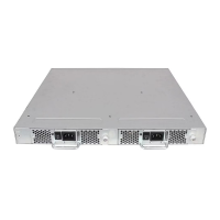
Replacing the 8/40 SAN Switch power supply and fan
assembl y
CAUTION:
Disassembling any part of the power supply and fan assembly voids the warranty and regulatory
certifications. There are no user-serviceable parts inside the power supply and fan assembly. Because
thecoolingsystemreliesonpressurizedair,donotleaveanyofthefanassemblyslotsemptylongerthan
two minutes while the switch is operating. If a fan assembly fails, leave it in the switch until it can be
replaced. Maintain all fan assemblies in operational condition to provide redundancy.
Replacing the power supply and fan assembly unit takes approximately t wo minutes. You will need:
• 8/40 SAN Switch
• New power supply and fan assembly FRU (one unit)
• Phillips-head screwdriver #1
To replace the power supply and fan assembly unit:
1. Unscrew the captive screw on the power supply fan assembly you are replacing using a Phillips-head
screwdriver.
2. Remove the power supply fan assembly you are replacing from the chassis by pulling the handle
out, away from the chassis.
3. Install the new power supply fan assembly unit in the chassis:
a. Orient the new fan assembly with the captive screw on the right.
b. Gently push the power supply fan assembly into the chassis until it is firmly seated.
CAUTION:
Do not force the installation. If the power supply fan assembly does not slide in easily,
ensure that it is correctly oriented before continuing.
c. Secur e the fan assembly to the chassis by screw ing in the c aptive screw using the P hillips-head
screwdriver.
4. Ver
ify that the fan status LED is lit steady green to indicate normal operation.
5. Op
tionally, display the fan status using the fanShow command from the CLI.
56
Operating the 8Gb SAN Switch
 Loading...