3. Install the new fan assembly in the chassis:
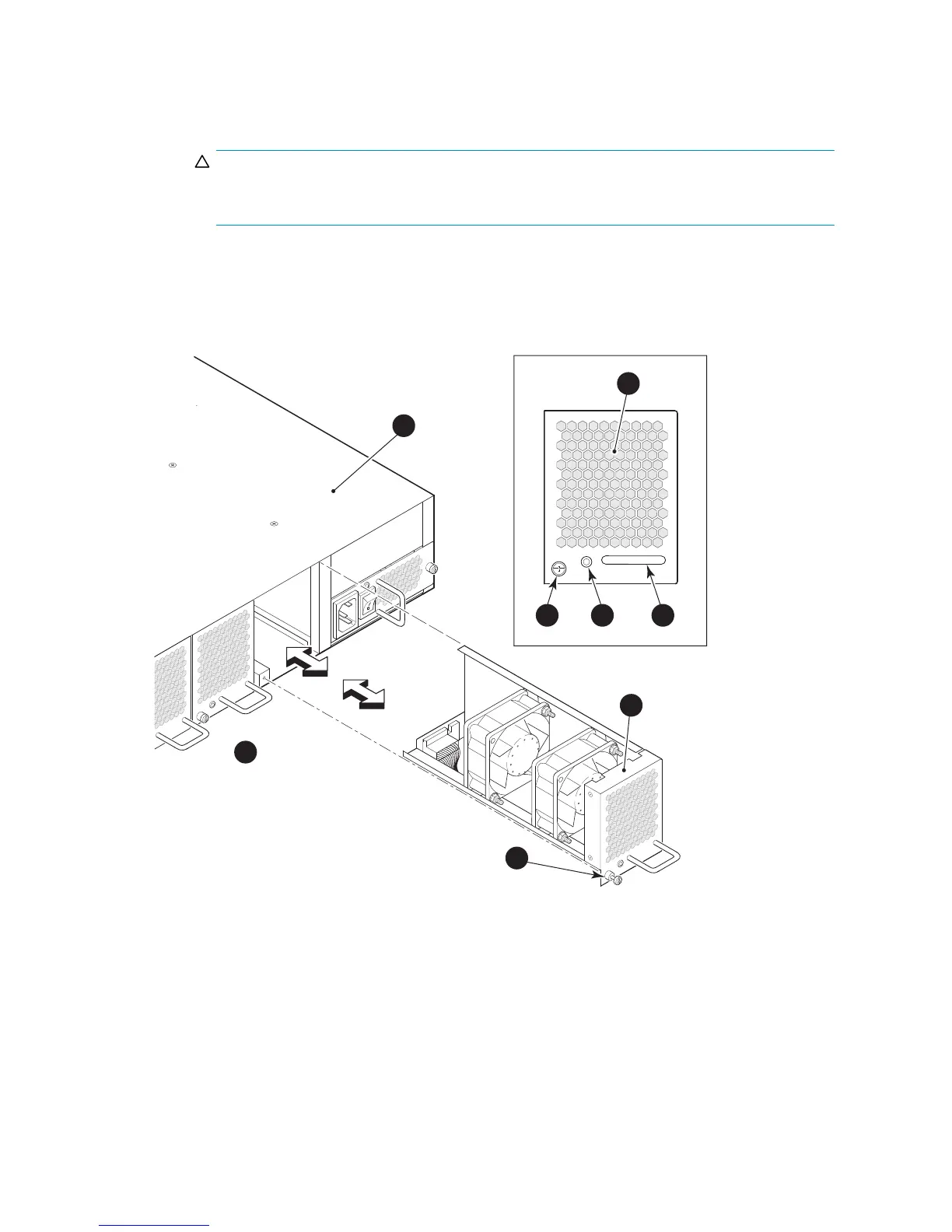
a. Orient the new fan assembly as shown in Figure 26,withthecaptivescrewontheright.
b. Gently push the fan assembly into the chassis until it is fi rmly in.
CAUTION:
Do not force the installation. If the fan assembly does not slide in easily, ensure that it
is correctly oriented before continuing.
c. Secure the fan assembly to the chassis with the captive screw.
4. Verify that the fan status LED is lit steady green to indicate normal operation (see Table 12).
5. Optionally, display the fan status using the fanShow command from the CLI (see Figure 26 for the
locations of Fan assembly #1, F an assembly #2, and Fan assembly #3).
scale: 1/4" = 1"
Scale:
3/8" = 1"
26461a
1
2
2
3
3 4
5
6
18/80SANSwitch
4 Status LED
2 Fan assembly unit 5. Handle
3 Captive screw
6. Nonport side
Figure 26 Inserting the fan assembly in the 8/80 SAN Switch
8Gb SAN Switch hardware reference manual
59
 Loading...