Power on the 8
Gb SAN Switch
The8/8and8/24SANSwitchesuseonepowercord. The8/40and8/80SANSwitchesusetwo
power cords. To p ower on:
IMPORTANT:
The 8/8 and 8/
24 SAN Switches do not have an on/off switch. Power is supplied as soon as you
connect it to an AC power source.
1. Connect the power cord(s) to a power inlet on the switch and to a power source. Verify that the
cord(s) use a minimum service loop of 6 inches, to av oid stress.
IMPORTANT:
To protect against AC failure on the 8/40 SAN Switch or the 8/80 SAN Switch, connect
each power cord to outlets on separate circuits.
2. For the 8/40 and 8/80 SAN Switches, set the two AC switches to the ON position (1). Power is
supplied to the switch as soon as the first power supply is connected and turned on.
The power supply LEDs display amber until POST completes, and then change to green. The switch
usually requires from 1 to 3 minutes to boot and complete POST.
3. After POST completes, verify that the switch Power and Status LEDs light are green.
Make a serial connection
All basic
configuration tasks require a serial connection:
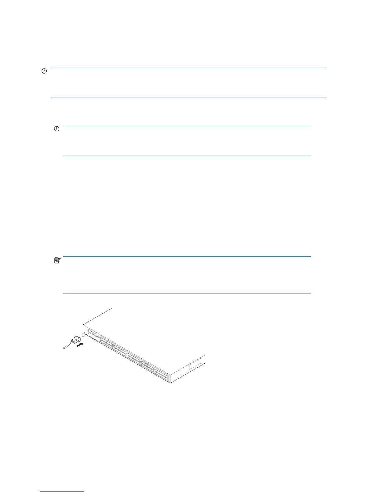
1. Connect the serial cable to an RS-232 serial por t on the workstation, as shown in Figure 18. Figure
18 shows the 8/24 SAN Switch; however, this procedure is similar for all SAN Switches.
NOTE:
If the serial port on the workstation uses an RJ-45 connector instead of an RS-232
connector, remove the adapter on the end of the serial cable, and insert the exposed RJ-45
connect
or into the RJ-45 serial port on the workstation.
A
T
T
EN
T
I
O
N
:
M
axi
m
um
scre
w
l
ength for rack
m
ounti
ng
to
be 5m
m
or 13
/64
in
.
26473a
10
11
16
17
18
19
24
25
26
27
32
33
34
35
12
13
14
15
20
21
22
23
28
29
30
31
36
37
38
39
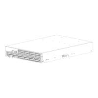
H
P S
tora
ge
W
or
ks 8/4
0
SAN
S
w
it
ch
Figure 18 Connecting the s erial ca b le
2. Close any serial communication programs running on the workstation.
40
Installing and configuring an 8Gb SAN Switch
 Loading...