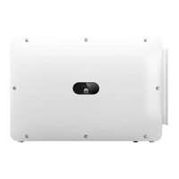
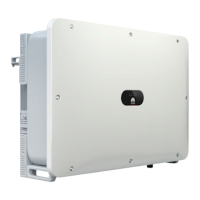
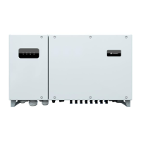
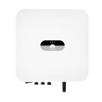
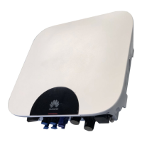
Figure 3-2 Ports on the power module
(1) DC SWITCH (PV
maintenance switch)
(2) PV input ports (3) Battery input ports
(4) COM-PAR
(communications port between
parallel power modules)
(5) COM-BAT
(communications port between
power module and battery
module)
(6) Reserved port
(7) Maintenance compartment
door
(8) Ground point (9) AC input
(10) AC output (11) Reserved port (12) DIP switch
(13) FE ports (14) COM and dry contact
ports
(15) WiFi switch
(16) Manual ON/OFF switch
DIP Switch
Figure 3-3 DIP switch
Table 3-1 DIP switch description
Parallel
Power
Module
CAN
Address
Pin 1
(M/S)
Pin 2 (A) Pin 3 (B) Pin 4 (C) Remarks
1 ON OFF OFF OFF Master
address
2 OFF ON OFF OFF Slave
address
iSitePower-M V100R002C00 User Manual
(MAP05A1, MAB05B1)
iSitePower-M V100R002C00 User Manual
(MAP05A1, MAB05B1) 3 Components
Issue 01 (2022-07-15) Copyright © Huawei Technologies Co., Ltd. 28

 Loading...

