English - 22
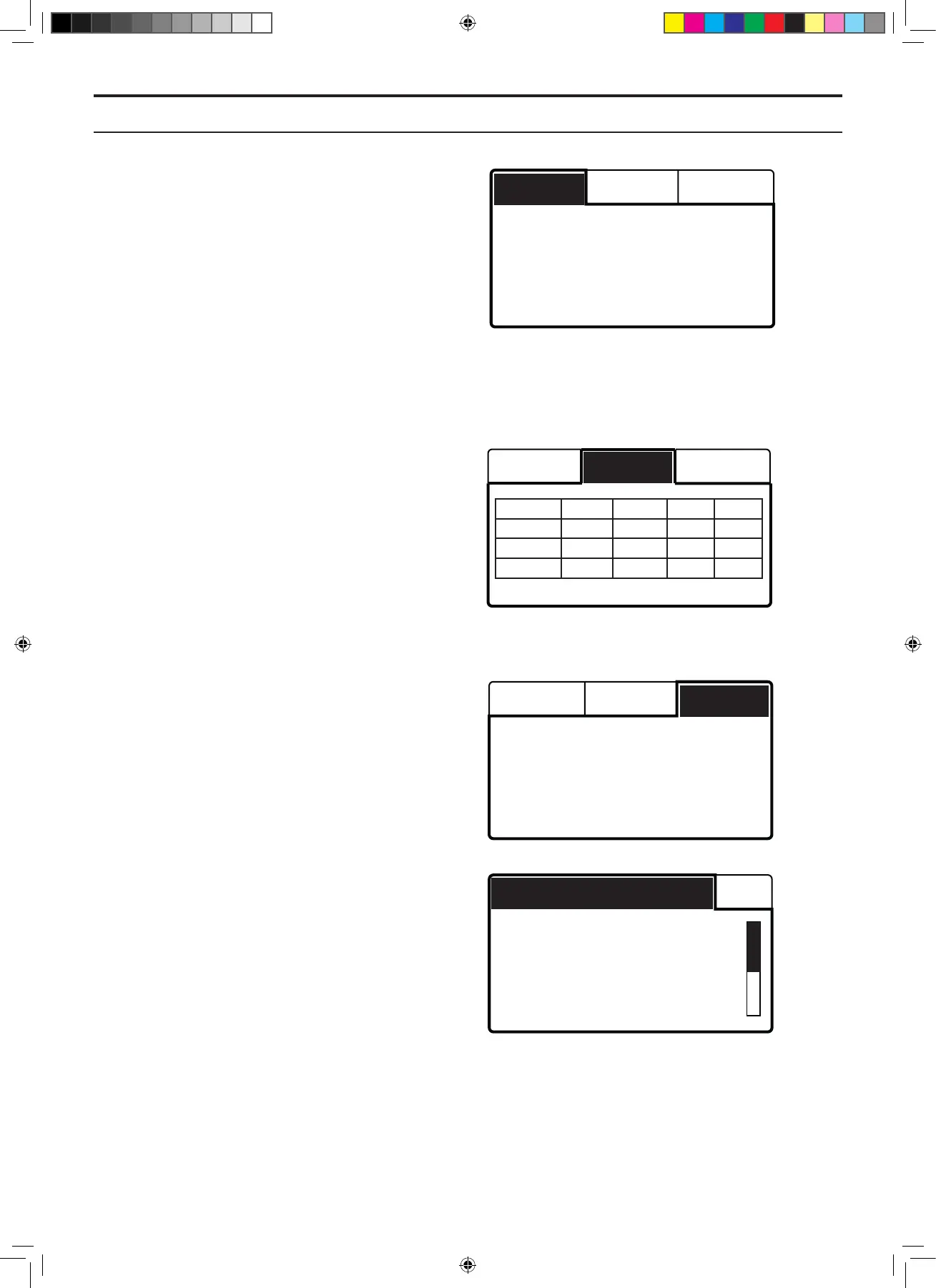
The Info - Loop - A signal display mode shows the
loop signal from the boundary loop measured through
the loop sensors in the mower. The value should lie
between approximately 40 and 320 to ensure good
functionality. The closer to the loop the mower is,
the higher the value. When the robotic lawnmower
is directly over the loop, the value is 0 and when the
mower is outside of the loop, the value is negative.
The A signal is shown for all four loop sensors:
• Front L: Front left loop sensor
• Front R: Front right loop sensor
• Rear L: Rear left loop sensor
• Rear R: Rear right loop sensor
The Info - Loop - G, F, N display mode shows the loop
signals from the Guide wires and the F and N elds
measured through the loop sensors on the mower.
The signals are shown for all four loop sensors:
• FL: Front left loop sensor
• FR: Front right loop sensor
• RL: Rear left loop sensor
• RR: Rear right loop sensor
To ensure good functionality in guide wires, the value
for the Guide signal should be (-) 70 - 120 beside each
guide wire.
The Info - Loop - Quality display mode shows the loop
system’s signal quality measured through the loop
sensors in the mower. The loop signals can only be
interpreted if the value for Quality is 100%. If the value
is 99% or lower, the loop system does not function
correctly and thus none of the values displayed for the
signals are correct.
The Info - Loop - Quality also shows if the mower is in
the charging station or not.
The Info - Sensors - Status display mode shows:
• Collision, front and Collision, rear: One way
of testing the collision sensor is to hold the
mower chassis by the stop button and move
the body forward and back with the handle
at the rear. The display shows Yes or No.
Continue to press on the body until you see
that the collision sensors work.
• Lifted: To test the lift sensors, lift up the front
part of the body. When the body is lifted up
the lift sensor is activated and the mower’s
display shows Yes. When the mower is in the
lowered position No is displayed.
Collision, front No
Collision, rear No
Lifted No
Tilted, X 0°(0%)
Status Temp
A-signal, front L 150
A-signal, front R 148
A-signal, rear L 140
A-signal, rear R 142
A loop G, F, N Quality
A-loop G, F, N Quality
Signal quality 100%
In charging station No
FL FR RL RR
G1 280 282 270 273
F 324 322 274 270
N 110 108 98 97
A-loop G, F, N Quality
2. SPECIAL MENU FUNCTIONS
TH_1158203_310_315_GARDENA_US.indd 22 2016-05-11 10:16:01