English - 70
To change the lter:
1. Remove the damaged lter.
2. Clean thoroughly around the mounting
surfaces.
3. Apply the new lter, ensuring the adhesive
surfaces fasten properly to the chassis.
4. Ret the lter cover and body.
5.14 Replacing the sensors
5.14.1 Front loop sensors
The front loop sensors are mounted on the front
sensor circuit board. The sensors cannot be replaced
separately. The entire front sensor circuit board must
be replaced as a unit.
1. Disassemble the body. See 5.2.1
Disassembling the body on page 59.
2. Disassemble the chassis. See 5.2.2
Disassembling the chassis on page 59.
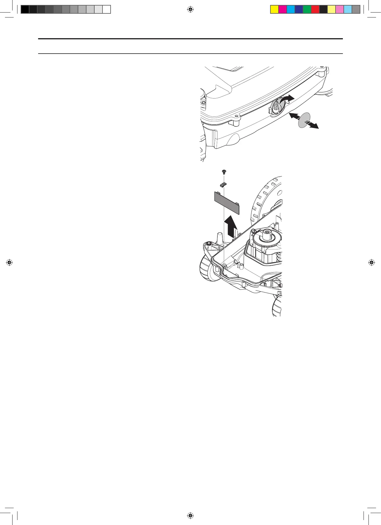
3. Disconnect the cable from the front sensor
circuit board. Note: Always pull the connector
and NOT the cable.
4. Unscrew the screw (Torx 20) which secures
the holder for the front sensor circuit board.
5. Fit the new front sensor circuit board and
reconnect the cable.
6. Ret the chassis and body.
5.14.2 Rear loop sensors and tilt sensor
The rear loop sensors and tilt sensor are part of the
main circuit board. The sensors cannot be replaced
separately. The entire main circuit board must be
replaced as one unit. See 5.8 Replacing the main
circuit board on page 65.
5.14.3 Lift sensor
The magnet on the collision column must be tted
correctly if the lift sensor is to work. If this is not the
case, the components in the front collision column
must be replaced. See 5.18 Replacing the front
collision column / lift sensor on page 74.
To replace the lift sensor circuit board:
1. Disassemble the body. See 5.2.1
Disassembling the body on page 59.
2. Disassemble the chassis. See 5.2.2
Disassembling the chassis on page 59.
5. REPAIR INSTRUCTIONS
TH_1158203_310_315_GARDENA_US.indd 70 2016-05-11 10:16:33