EasyManuals Logo

Husqvarna AUTOMOWER 310 Technical Manual

Husqvarna AUTOMOWER 310
100 pages
To Next Page IconTo Next Page
To Previous Page IconTo Previous Page
Page #75 background imageLoading...
Page #75 background image
English - 75
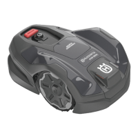
To replace the sleeve for the lift sensor, the lift
sensor circuit board must also be removed by
bending the snap-on fastener.
6. Ret all components, the chassis and body.
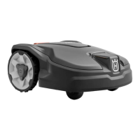
5.19 Changing and regreasing lower
front wheel bearing
1. Disassemble the body. See 5.2.1 Disassembling
the body on page 59.
2. Dismantle the front wheel by loosening the three
screws on the side of the wheel and then splitting
the wheel.
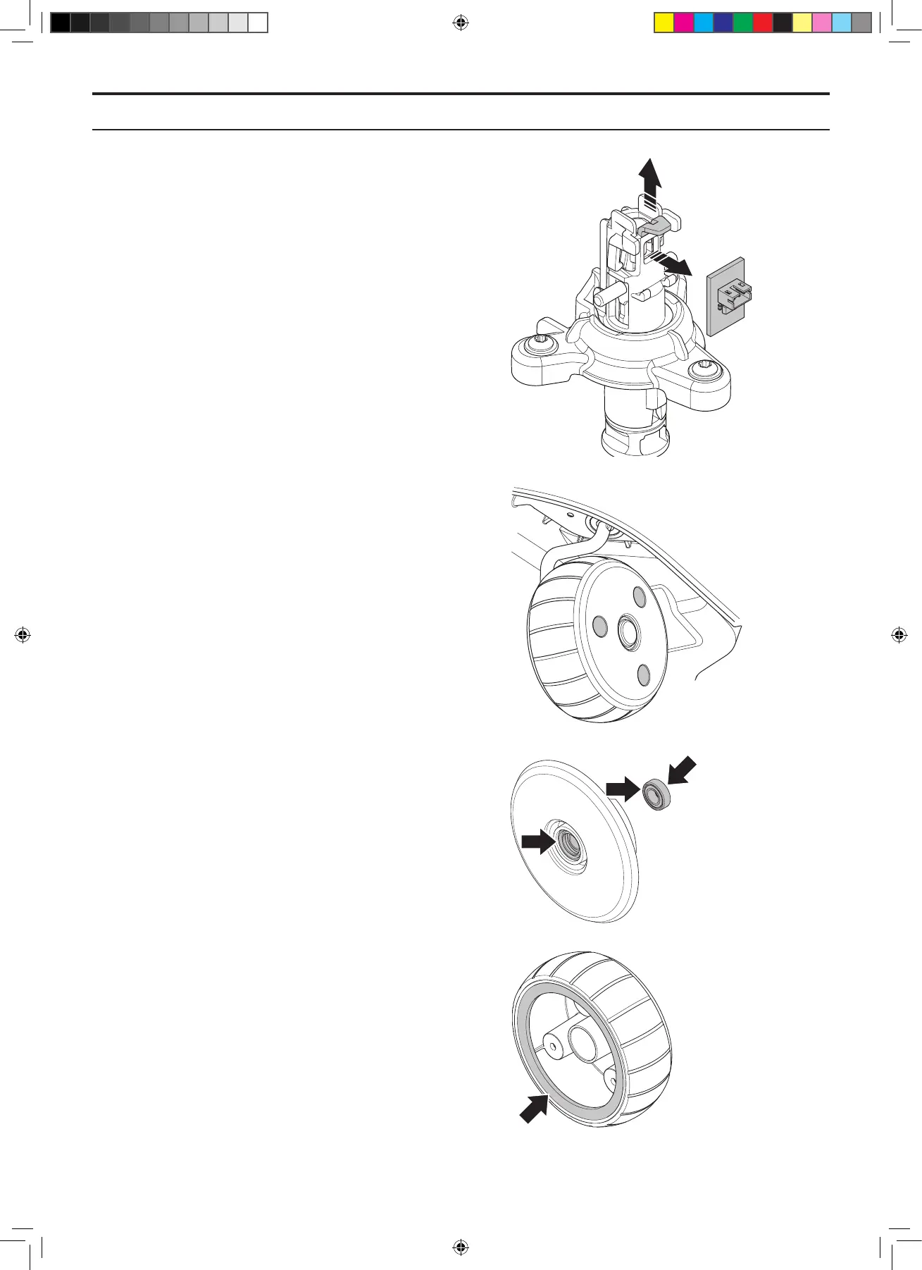
3. Remove the lock washer from the axle.
4. Remove the washer, ball bearing and the inner
front wheel half from the axle.
5. Apply grease to both ball bearings.
6. Ret the inner front wheel half, ball bearing and
washer.
7. Fit a new lock washer onto the axle. NB! Do
not reuse the old washer as this will not give a
satisfactory lock after being removed from the
axle.
8. Apply grease to the outer front wheel half before
assembling.
5. REPAIR INSTRUCTIONS
TH_1158203_310_315_GARDENA_US.indd 75 2016-05-11 10:16:40

Table of Contents

Other manuals for Husqvarna AUTOMOWER 310

Questions and Answers:

Question and Answer IconNeed help?

Do you have a question about the Husqvarna AUTOMOWER 310 and is the answer not in the manual?

Husqvarna AUTOMOWER 310 Specifications

General IconGeneral
Cutting Width22 cm
Cutting Height Min20 mm
Cutting Height Max50 mm
Battery TypeLi-ion
Typical Charging Time60 min
Typical Mowing Time per Charge70 min
Maximum Incline Within the Working Area40%
Working Area Capacity1000 m²
Battery Capacity2.1 Ah
Weight9.4 kg
Battery Voltage18 V
Operating Time70 min
Maximum Area1000 m²
Weather ResistanceYes
Smart ConnectivityNo
Blade TypePivoting razor blades

Related product manuals