English - 35
3 Installation
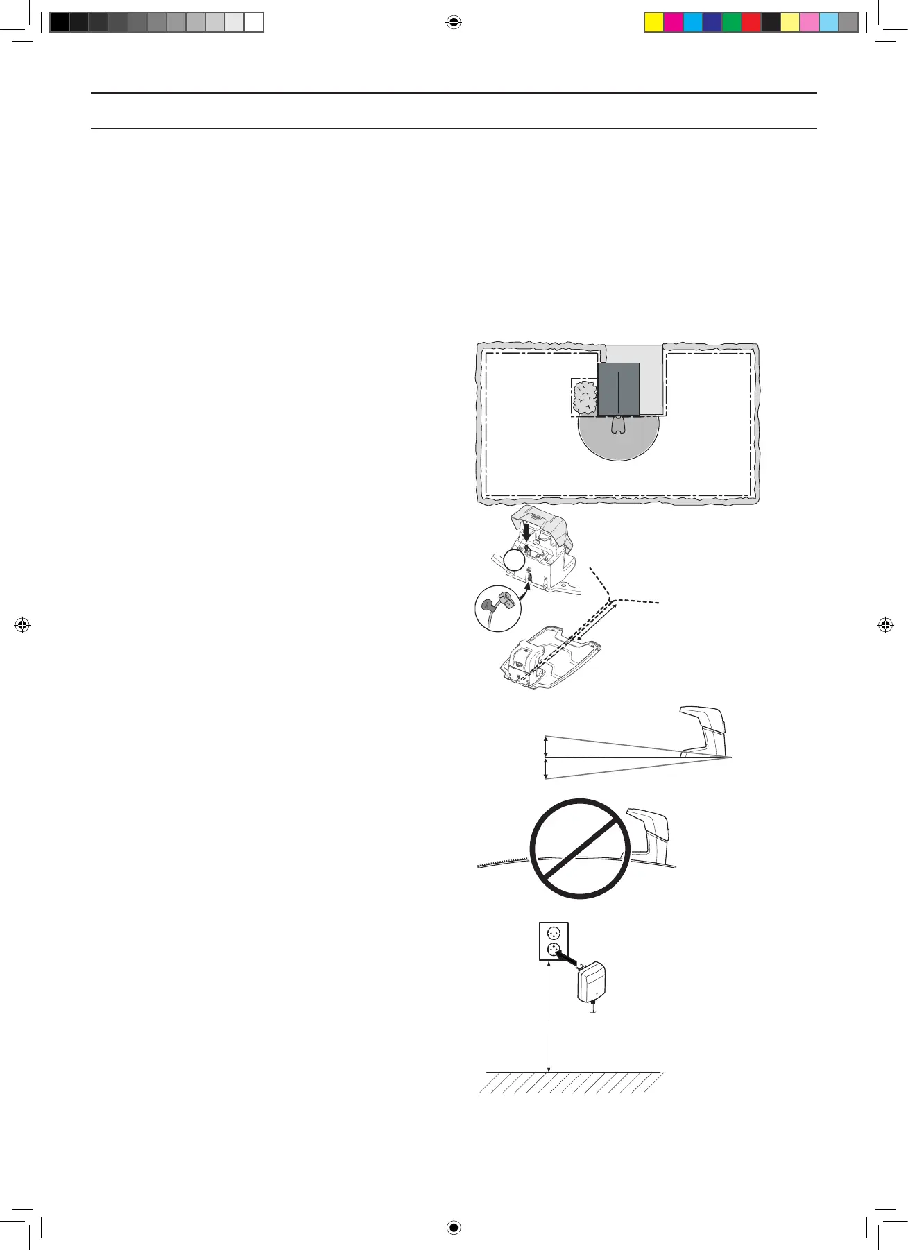
3.1 Charging station
The placement of the charging station should be
well planned in order to give the best installation
and operation of the robotic lawnmower. See 3.2
Installation of the charging station in the Operator’s
Manual.
• The charging station should have a central
position in the working area so that the
robotic lawnmower is close to it from all
parts of the installation.
• The charging station must be positioned so
that the boundary wire can be laid 1.5 m
/4.9 ft straight out to the left and 1.5 m /
4.9 ft straight to the right from the charging
station. See the Operator’s Manual.
• The charging station must be positioned so
that the guide wire can be laid
2 m / 0.08 ” straight out from the front edge
of the charging station.
• The charging station must be positioned
so that the entire guide loop is not too long.
The guide loop should not be longer than
about 400 m / 1 300 ft.
The guide loop is dened as the guide wire
from the charging station to the T-connector
in the boundary loop plus the boundary wire
from the T-connector to the charging station,
going left from the T-connector. See 3.3
Guide wire on page 38.
• The charging station must be positioned on
relatively level and even ground. See the
illustration.
• The battery is spared if charged in the lowest
possible ambient temperature. Consequently,
it is benecial if the charging station can be
placed where it is shaded, especially during
the warmest parts of the day.
• The power supply must be placed where
it is well ventilated and is not exposed to
direct sunlight. Under no circumstances
may it be enclosed in any form of small box
or plastic bag. The power supply should be
placed under a roof, preferably indoors.
• The power supply must be mounted on
a vertical surface, such as a wall or a fence.
Screw the power supply in place using
the two eyelet connectors. No screws are
supplied. Select screws suitable for the
material in question.
G1
Max 5 cm/12"
Max 5 cm/12"
min 30cm/12”
Min 2 m / 7 ft
3. INSTALLATION
TH_1158203_310_315_GARDENA_US.indd 35 2016-05-11 10:16:08