English - 67
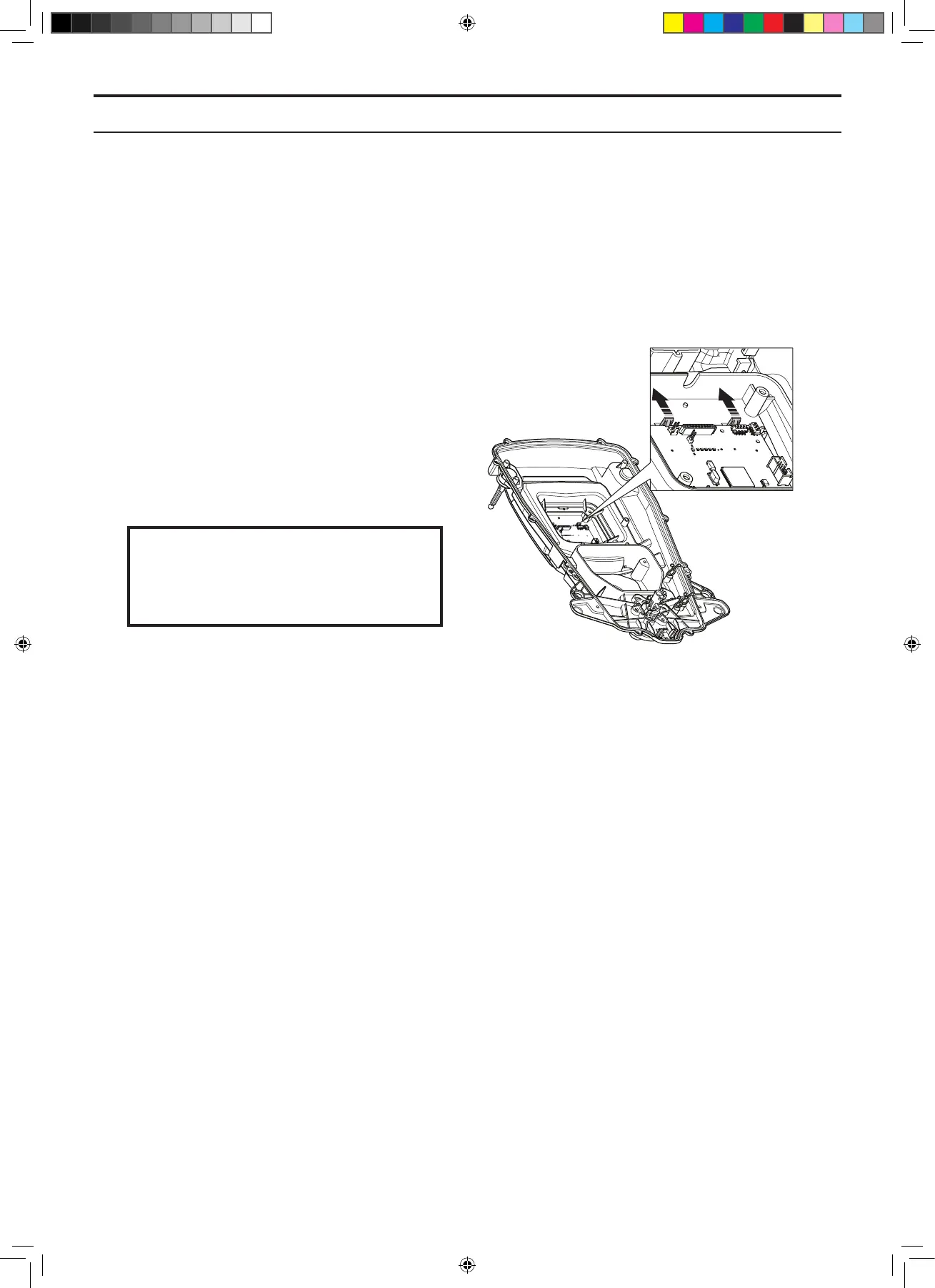
5.10 Replacing the HMI circuit
board
1. Disassemble the body. See 5.2.1 Disassembling
the body on page 59.
2. Disassemble the chassis. See 5.2.2
Disassembling the chassis on page 59.
3. Disconnect all connections from the
connectors on the HMI circuit board.
4. The HMI circuit board is secured to the display
cover by means of two snap-on fasteners.
Carefully bend away the snap-on fasteners
and lift the HMI circuit board in the edge on
which the snap-on fasteners are located.
5. Remove the HMI circuit board.
6. Fit a new HMI circuit board. Carefully bend
away the snap-on fasteners to make it easier
to t the HMI circuit board.
Only touch the edges of the circuit board.
Never touch the board’s components and
pin terminals.
IMPORTANT INFORMATION
7. Reconnect all cables to the HMI circuit board.
8. Ret the chassis and body.
9. Put the main switch in position 1 and connect
the mower to Autocheck EXP to program the
HMI circuit board. See 4.3.4 Programming on
page 49.
5. REPAIR INSTRUCTIONS
TH_1158203_310_315_GARDENA_US.indd 67 2016-05-11 10:16:31