English - 56
subsequently become the conditions for the main
circuit board to take into account in evaluating the
sensor signals. The HMI circuit board also has the task
of presenting information from the main circuit board
to the display.
The main circuit board and the HMI circuit board and
the GARDENA Smart system board contain their own
separate software. If any of these boards are replaced,
they have to be programmed via Autocheck EXP.
A new HMI circuit board contains software but, after
being tted, it must always be programmed to be
updated to latest version.
The other circuit boards do not have any software,
and consequently do not need to be programmed after
a replacement.
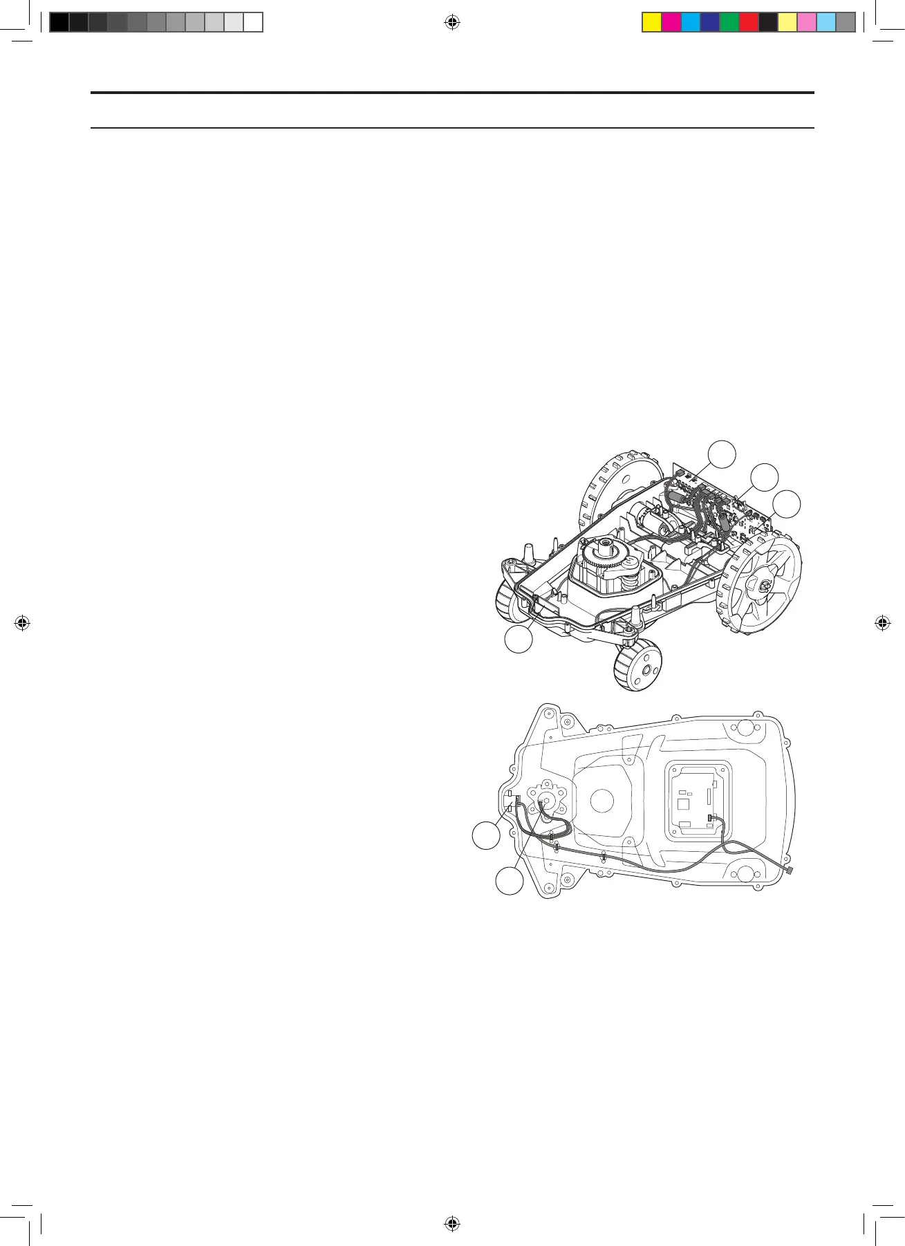
5.1.3 Sensors
The robotic lawnmower is equipped with the following
sensors:
• Front collision sensor (1)
• Rear collision sensor (2)
• Tilt sensor (3)
• Lift sensor (4)
• Rear loop sensors (5)
• Front loop sensors (6)
The tilt sensor, the rear loop sensors and the rear
collision sensor are tted on the main circuit board in
the lower section of the chassis. The other sensors are
tted to their own small circuit boards.
The sensors cannot be repaired. If troubleshooting shows
that one of the sensors is faulty, the entire circuit board
(depending on which sensor is faulty) must be replaced.
The task of the loop sensors is to measure the signals
the circuit board in the charging station sends along
the boundary loop (A signal), the guide loops (guide
signals) and the antenna plate (F and N signals).
The signals are used to control the mower and keep
the mower inside the working area.
The lift sensors and the collision sensors measure the
magnetic eld from the two permanent magnets that
are located in the body. If the magnetic eld decreases
(the distance to the magnet increases) the main
circuit board interprets that the mower has been lifted
or a collision has occurred.
The tilt sensor is an accelerometer positioned on the
main circuit board. It measures the gradient in both
X and Y axis. The value is used, among other things,
to correct the speed of the drive wheels when mowing
on steep slopes.
The current value from the sensors can be read in the
display on the mower, as well as in Autocheck EXP.
6
3
2
5
1
4
5. REPAIR INSTRUCTIONS
TH_1158203_310_315_GARDENA_US.indd 56 2016-05-11 10:16:16
 Loading...