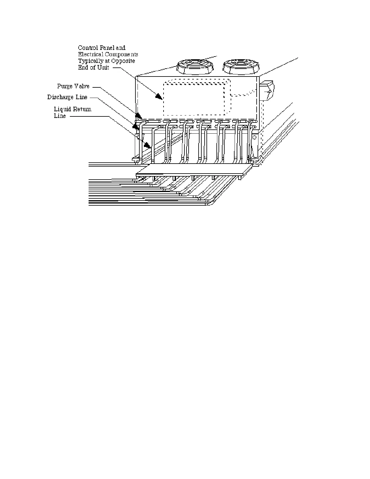
Connecting to One Manifold
Route the discharge line directly to its respec-
tive condenser inlet stub and install a purg e
valve at the highest point in the line Route the
liquid return line in a manner providing free
trapless drainage from the condenser to the
connection at the compressor unit. Horizontal
piping runs must be pitched in direction of
flow.
Connecting to Two Manifolds
When a compressor unit is served by two sets
of condenser circuits, an expansion loop must
be constructed between the manifolds.
Note: a connection is provided on the rack for
7
⁄8 inch equalizer line. The use of an equalizing
line is left to the discretion of the store engi-
n e e r. It is recommended that the condenser
m a n u f a c t u r e r’s installation instructions be
consulted. When used, the equalizing line
should have a field supplied check valve
installed to prevent flow from the condenser
to the receiver. A s h u t o f f valve should be
installed on the condenser side of the check
valve. Normally, equalizer lines are not
required unless the condensate lines are
trapped and/or undersized.
1. D i s c h a r ge line: Connect the two inlet
stubs to the discharge line by forming an
expansion loop extending at least
1 2 inches away from the manifolds. Do
not route the discharge line directly in
front of the control panel.
2. Liquid return line: Route each liquid
return line downward at least 6 f e e t
between outlet stubs before teeing into
the main liquid return line. (Note: If split
condenser valving is not used, drop may
be reduced to 2 feet.) After the tee, route
the main liquid return line in a manner
providing free trapless drainage from the
condenser to the connection at the com-
pressor unit.
HUSSMANN CORPORATION • BRIDGETON, MO 63044-2483 • Printed in USA
CONDENSER INSTALLATION Addendum – April 15, 1996
A - 4
Figure A-3. Connecting to One Manifold