temporarILy power tHe SenSorS
The sensors are not receiving power until the gate operator receives a command to run (open or close command). To
temporarily power sensors and check that the gate operator is monitoring the sensors properly, turn on Photo Eye Align
by taking the following steps:
1. Access the User Menu and select PE.
To access the User Menu, press the Menu button twice. For a refresher on
using the Menu Mode navigational buttons, refer to the chart below.
2. Press NEXT and continue to press NEXT until PE 0 (OFF) appears.
3. Press SELECT.
PE characters begin blinking.
4. To turn ON photo eye alignment and temporarily power the sensors, press
NEXT so PE 1 (ON) appears.
5. Press SELECT.
PE stops blinking.
6. Press MENU to exit Menu Mode and return to Run Mode.
NOTE: NOTE: The Photo Eye Align mode turns OFF with the next limit contact.
Controller Temporarily apply Power to Sensors LED Status
Smart DC PE 1 (ON)
PHOTO EYE ALIGN
When PE is ON, the LEDs associated with the sensor devices will be lit
if the sensors are properly connected and sensors are grounded. The
LEDs turn off when the ground circuit is removed.
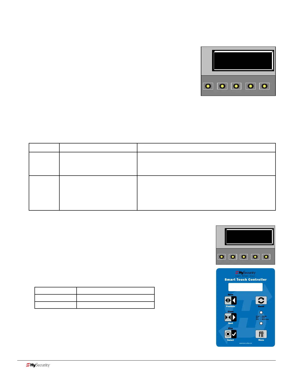
Smart Touch PE 1 (ON)
PHOTO EYE ALIGN
LEDs next to the sensor connections will be lit when no power is being
applied. When PE is turned ON, the LEDs turn off. If they do not turn
off, check for wiring issues such as a short or misapplied relay COM
connections. See CAUTION. If error messages appear on the display,
refer to Table 7: Troubleshooting Codes on page 14.
pHoto eye aLIGnment
Most photo eyes require careful optical alignment in order to aim the emitter
beam to the center of the receiver or reector. In order to avoid false triggering, it is
important to carefully align the system.
Align the photo eyes using this feature by taking the following steps:
1. Follow steps 1 through 6 in Temporarily Power the Sensors.
2. Move the photo eyes (up/down, side to side) to align the emitter beam.
Audible Chirp Beam Aligned ??
One No
Two Yes
3. When the buzzer chirps twice, indicating the photo eyes are aligned, set the next
photo eye (if the site has one) and continue the process until all photo eyes are
aligned.
4. Run the gate with an open or close command. When any limit is triggered, the
User Menu item PE resets to zero (OFF).
NOTE: To cover the potential entrapment areas, mount photo eyes preferably within 5 inches
(13 cm) of the gate face. For more information, refer to ASTM F2200 Gate and Fence Standards.
PE 0 (OFF)
PHOTO EYE ALIGN
OPEN
CLOSE
STOP
MENU
RESET
PREV
NEXT
SELECT
Smart DC display and keypad
PE 1 (ON)
PHOTO EYE ALIGN
OPEN
CLOSE
STOP
MENU
RESET
PREV
NEXT
SELECT
PE 1 (ON)
PHOTO EYE ALIGN
12 D0726 Rev. J UL 325 - 2016 HySecurity Monitored Sensors © 2016 www.hysecurity.com