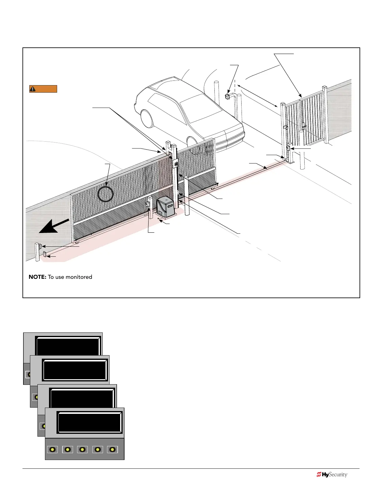
dIaGram 5: typIcaL SLIdeSmart dc SIte aSSeSSment
NOTE: To use monitored entrapment protection sensors for all four areas called out in this site scenario, The Solution multi-
input device would be required. Refer to page 6. Note that every site is different. All potential entrapment zones should be
protected with contact or non-contact sensors.
Left Hand Gate
opening
ENTRAPMENT
6 ft (1.8 m) minimum
ZONE
Public Side
Secure Side
Gap between vertical bars
must be less than 2¼” (57 mm)
If gap is larger, a screened wire
mesh must extend to top of gate
or, to a minimum height
of 6 ft (1.8 m).
Photo eye (Emitter or Reector in the Open direction)
Physical stop - at both ends of gate rail.
Photo eye (Receiver)
Earth ground
Interior posts,
Non-pinch
rollers (2x)
WARNING
Be sure to place the
WARNING signs on both
sides of the gate in clear view.
For your records, take a photograph of
the completed installation site.
Mount access control
devices at least 6 ft
(1.8 m) beyond the gate.
Pedestrian gate located
near the slide gate.
Make sure a separate walk-
through entrance is available
and its pedestrian path is
clearly designated.
Photo eye
Emitter or Reector
(Close direction)
Physical
stop
V track
(gate rail)
Photo eye (Receiver)
Edge sensors (Public and Secure sides)
(Draw-in zone)
NOTE: Any gap larger than 2¼” (57 mm)
between gate and xed objects must be
protected. Install wrap around edge sensors
where gap between post and gate creates a
draw-in zone.
After wiring your external entrapment protection sensors to the Controller’s sensor inputs, access the Installer Menu. Set
sensors S1, S2, and S3 for this example of a site scenario, as follows:
GATE OPERATOR: SlideSmart DC and SlideSmart DCS using multi-input device.
S1 0
SENSOR #1 TYPE
OPEN
CLOSE
STOP
MENU
RESET
PREV
NEXT
SELECT
S1 5 (EDGE OPEN)
SENSOR #1 TYPE
OPEN
CLOSE
STOP
MENU
RESET
PREV
NEXT
SELECT
S2 5 (EDGE OPEN)
SENSOR #2 TYPE
OPEN
CLOSE
STOP
MENU
RESET
PREV
NEXT
SELECT
S3 7 (EYE BOTH)
SENSOR #3 TYPE
OPEN
CLOSE
STOP
MENU
RESET
PREV
NEXT
SELECT
Initial SENSOR setting = 0
Set SENSOR 1 = #5
EDGE OPEN (public side)
Set SENSOR 2 = #5
EDGE OPEN (secure side)
Set SENSOR 3 = #7
EYE BOTH **
**Since in the site scenario there are two monitored photo eye sensors protecting open and close
directions of travel and only one input remaining, you could use a Multi-input device (The Solution).
Connect sensors to two separate inputs on The Solution, set to NC contact (not Pulse) and wire The
Solution output to SENSOR 3 on the Controller. In the Installer Menu, set SENSOR #3 TYPE to EYE
BOTH. Another option? Use a long range photo eye and wire as a singular SENSOR input 1.
22 D0726 Rev. J UL 325 - 2016 HySecurity Monitored Sensors © 2016 www.hysecurity.com
www.hysecurity.com © 2016 Quick Start D0726 Rev. J 23