PARTIAL
OPEN
EYE
EXIT
LOOP
EXIT
LOOP
LOOP
LOOP
EDGE
EYE
COM
+ 24 V
EMERG
OPEN
SHOW
LEDs
SENSOR 2
SENSOR 3
SENSOR 1
SENSOR
COM
EXIT
LOOP
BLOCK
EXIT
CENTER
LOOP
IN OBS
LOOP
OUT OBS
LOOP
11
10
9
8
7
6
5
4
3
2
1
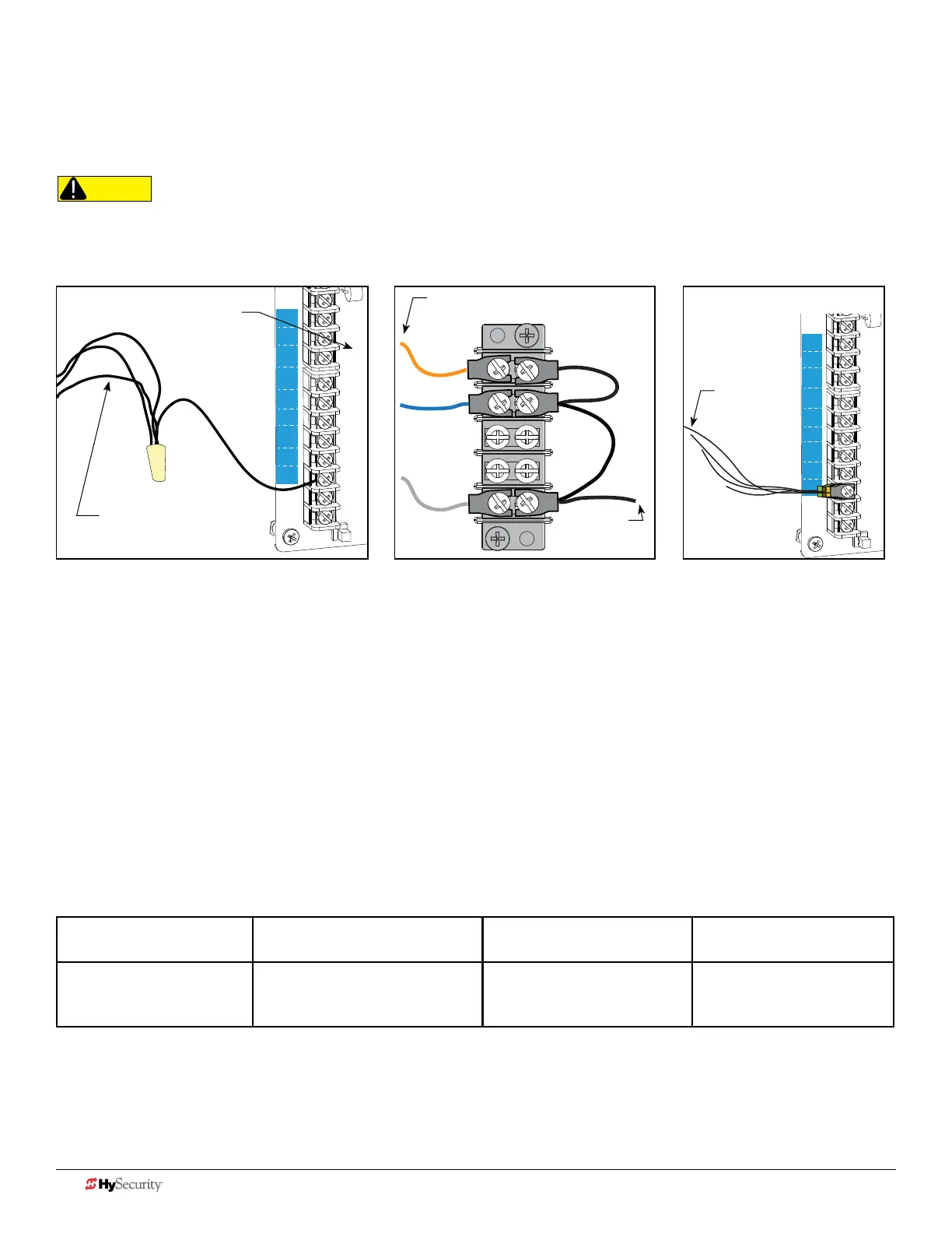
wIrInG tIpS for SenSor com termInaL: Smart dc
If using multiple sensor devices, use a wire nut as a junction and pigtail to SENSOR COM. Or, stack locking spade
connectors. Or, install a separate terminal block and jumper outputs to one lead for SENSOR COM.
RADIO
OPEN
PARTIAL
OPEN
EYE
EXIT
LOOP
EXIT
LOOP
LOOP
LOOP
EDGE
EYE
COM
+ 24 V
EMERG
OPEN
SHOW
LEDs
SENSOR 2
SENSOR 3
SENSOR 1
SENSOR
COM
EXIT
LOOP
BLOCK
EXIT
CENTER
LOOP
IN OBS
LOOP
OUT OBS
LOOP
11
10
9
8
7
6
5
4
3
2
1
Wires coming
from sensor
device
Wires coming
from sensor
device
CAUTION
All external entrapment protection sensors must be NC sensor outputs and wired to the SENSOR COM terminal for
monitoring and powering purposes. The sensor becomes actively powered when the gate operator receives a run command.
Wire nut and pigtail to SENSOR COM Crimp spade on wire and stackAdd terminal block
Wires coming
from sensor
device
Wire to
SENSOR
COM
Reference numbers indicate terminal
location from base of controller.
menu mode naVIGatIonaL tIpS
The buttons on the display keypad perform certain functions while in Menu Mode. Refer to the chart.
To change data
appearing in the display
To navigate through
the Selections
To choose what appears
on the display
To navigate between
menu items
Press Select.
Two left characters blink.
Press Next or Previous.
Continue pressing Next to view
all selections.
Press Select.
Blinking characters
become static.
Press Next or Previous.
Advance - press Next
Previous - press Previous
36 D0726 Rev. J UL 325 - 2016 HySecurity Monitored Sensors © 2016 www.hysecurity.com