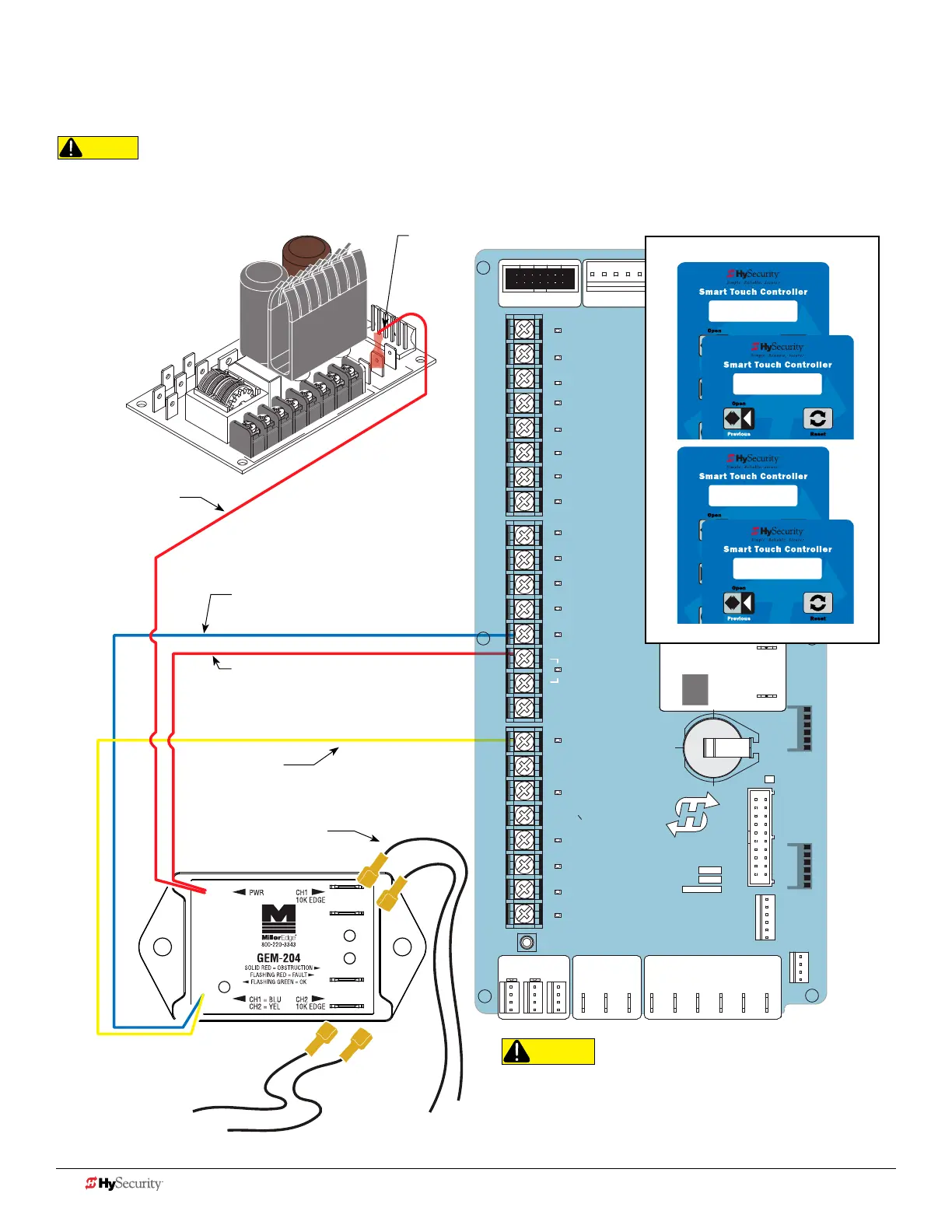
Smart toucH: 2 cH wIred edGe wItH Gem-204
The wiring diagram illustrates a WIRED edge receiver connected to the STC controller via GEM-204.
CAUTION
Connect all contact and non-contact sensors to same power source.
Example, Do NOT connect photo eyes to +24VDC and gate edges to
+12VDC. Incompatible electricity ow. A FAULT 2 will appear.
CAUTION
All external entrapment protection sensors must be NC
sensor outputs and wired to the SENSOR COM terminal for
monitoring and powering purposes. The sensor becomes
actively powered when the gate operator's motor runs.
24V
A
C A
cce
s
s
or
y powe
r
+
24
V
D
C
STOP BUTTON
OPEN BUTTON
CLOSE BUTTON
REMOTE OPEN AND
RADIO CONTROL
OPEN/CLOSE
1
OPEN PARTIAL
INTERLOCK OPEN
TIME CLOCK OPEN
FREE EXIT DETECTOR
DISABLE EXIT DETECTOR
DISABLE CLOSE TIMER
INSIDE OBSTRUCTION
VEHICLE DETECTOR
OUTSIDE OBSTRUCTION
VEHICLE DETECTOR
SHADOW/RESET
VEHICLE DETECTOR
SENSOR 1
SENSOR
COM
DO NOT USE
SENSOR 2
DO NOT USE
SENSOR 3
DO NOT USE
CHARGER
AC LOSS
LOCK INTERLOCK
EMERG CLOSE
FIRE DEPT OPEN
2
3
4
5
6
7
8
9
10
11
12
14
15
16
17
18
19
20
21
22
23
24
Smart Touch Controller
LIMIT DUAL GATE
RADIO OPTIONS
DRIVE
POWER
RS485
MOTOR USER 1
USER 2
USER 3
VEHICLE DETECTORVEHICLE DETECTORVEHICLE DETECTOR
STOP/BUZZER
FREE
EXIT
INSIDE
OBSTR
OUTSIDE
OBSTR
SHADOW
RESET
WIEGAND
HySecurity
COM
NO
MX000585
VERSION
S/N
RS232
DISPLAY
VEHICLE DETECTOR
COM COMA B
RPM
COMOPEN
S 1
+24V +24V
STATU S
LED
S2 0
SENSOR #2 TYPE
S2 3 (EDGE CLOS)
SENSOR #2 TYPE
S1 0
SENSOR #1 TYPE
S1 6 (EDGE BOTH)
SENSOR #1 TYPE
Red wire
Power +24V
Yellow wire
SENSOR connection for
CH 2
Blue wire
SENSOR Connection
for CH 1
CH 1 Wires to
10k Edge
CH 2 Wires to
10k Edge
NOTE:
Red wires are not
polarity sensitive.
Male spade
connector
Red wire SENSOR COM
The sensor does not become active
until a command is received by the
Controller and the motor runs.
Installer Menu Displays
Power Supply Board
Female quick
disconnects provided
34 D0726 Rev. J UL 325 - 2016 HySecurity Monitored Sensors © 2016 www.hysecurity.com