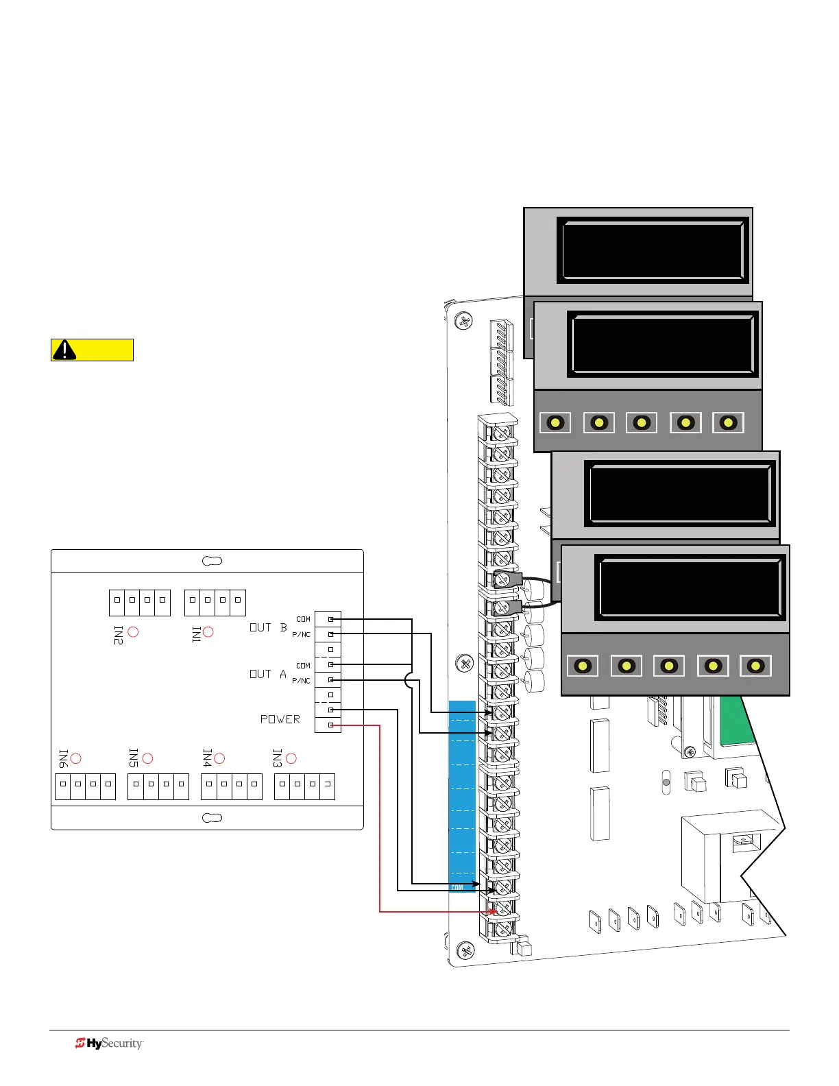
Smart dc: muLtI-Input moduLe (tHe SoLutIon, mIm-62)
Connect either output
(P/NC wire) to
SENSOR 1, 2, or 3.
1. Turn OFF AC power.
2. Input channels 1 and 2 must be used and are always assigned to OUTPUT A.
3. All other input channels may be congured to either A or B.
NOTE: If different sensor types are connected to the same output, then
program the Controller SENSOR type for EDGE options.
4. Turn ON power.
NOTE: Make sure both AC & DC switches are ON and the red battery
wire is plugged in.
5. Access the Installer Menu. Congure SENSOR
setting according to the types of sensors wired to
the Smart DC.
CAUTION
All external entrapment protection sensors must be NC
sensor outputs and wired to the SENSOR COM terminal
for monitoring and powering purposes. The sensor
becomes actively powered when the gate operator
receives a run command.
COM
COM
COM
COM
COM
COM
COM
COM
STOP
OPEN
RADIO
CLOSE
OPEN
OPEN
PARTIAL
OPEN
EYE
EXIT
LOOP
EXIT
LOOP
LOOP
LOOP
EDGE
EYE
COM
+ 24 V
EMERG
OPEN
SHOW
LEDs
S
1
+
24V
OP
EN
C
O
M
D
U
AL
G
A
T
E
C
O
M
A
B
U
S
E
R2
C
O
M
N
O
D
C
USER RELAY 1
Electro-mechanical
24VDC
24VDC
12VDC
12VDC
SENSOR 2
SENSOR 3
SENSOR 1
SENSOR
COM
EXIT
LOOP
BLOCK
EXIT
CENTER
LOOP
IN OBS
LOOP
OUT OBS
LOOP
S2 0
SENSOR #2 TYPE
OPEN
CLOSE
STOP
MENU
RESET
PREV
NEXT
SELECT
S2 6 (EDGE BOTH)
SENSOR #2 TYPE
OPEN
CLOSE
STOP
MENU
RESET
PREV
NEXT
SELECT
Installer Menu Settings
Examples in displays show
bi-parting swing gate site scenario.
S3 0
SENSOR #3 TYPE
OPEN
CLOSE
STOP
MENU
RESET
PREV
NEXT
SELECT
S3 6 (EDGE BOTH)
SENSOR #3 TYPE
OPEN
CLOSE
STOP
MENU
RESET
PREV
NEXT
SELECT
40 D0726 Rev. J UL 325 - 2016 HySecurity Monitored Sensors © 2016 www.hysecurity.com