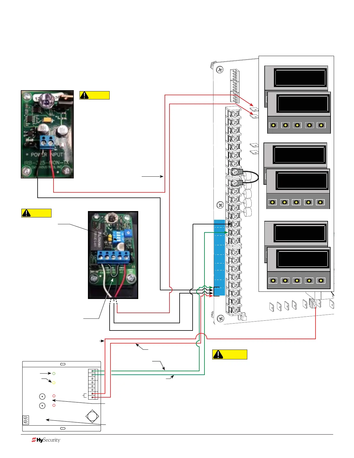
Smart dc: wIreLeSS edGe Gate LInK and pHoto eye
The wiring diagram illustrates a wireless edge receiver and a
photo eye connection. Refer to Photo Eye Alignment on page 12.
NOTE: Turn OFF AC power before connecting sensor wires to Smart DC.
To SENSOR COM
*Sensor wire (P/ NC) can
attach to any SENSOR input.
MGL - RX20
+24V
COM attaches to
SENSOR COM
POWER
STATUS
CH 1
CH 2
POWER
LEARN
OUTPUT
SELECT
CH 1 CH 2
COM
* P / NC
10K
COM
* P / NC
10K
+24V
Photo Eye
Transmitter
+24V
Green
Yellow
Miller Edge 2 Channel Wireless
Receiver (MGL - RX20)
CH 1 and CH 2 “LEARN” buttons.
Press the LEARN button on the Receiver for 2 seconds until the
amber light blinks continuously. Press the Edge or Test button on the Transmitter to complete
the LEARN mode process and sync the receiver and transmitter.
DIP switches for CH1 and CH2. Verify dip switch is set to “R” for each channel used. HySecurity uses NC
"Relay" sensors. Do NOT select "P" as the output. P = "Pulse" device.
MGL - RX20
CAUTION
Connect all contact and non-
contact sensors to same power
source. Example, Do NOT
connect photo eyes to +24VDC
and gate edges to +12VDC.
Incompatible electrical ow.
A FAULT 2 appears.
Antenna
COM
COM
COM
COM
COM
COM
COM
COM
STOP
OPEN
RADIO
CLOSE
OPEN
OPEN
PARTIAL
OPEN
EYE
EXIT
LOOP
EXIT
LOOP
LOOP
LOOP
EDGE
EYE
COM
+ 24 V
EMERG
OPEN
SHOW
LEDs
S
1
+
24V
OP
EN
C
O
M
D
U
AL
G
A
T
E
C
O
M
A
B
U
S
E
R2
C
O
M
N
O
D
C
USER RELAY 1
Electro-mechanical
24VDC
24VDC
12VDC
12VDC
SENSOR 2
SENSOR 3
SENSOR 1
SENSOR
COM
EXIT
LOOP
BLOCK
EXIT
CENTER
LOOP
IN OBS
LOOP
OUT OBS
LOOP
11
10
9
8
7
6
5
4
3
2
1
EMX IRB MON Photo Eye
Receiver
EMX IRB MON Photo Eye
Transmitter
+24V
NC Relay
COMMON / NEG.
to SENSOR COM
COMMON / NEG. to SENSOR COM
NOTE: DIP switches must
be set as shown otherwise
the photo eye will not
operate correctly. For easy
photo eye alignment,
CAUTION
Set DIP Switches
1 = OFF
2 = OFF
3 = OFF
4 = ON
CAUTION
All external entrapment protection sensors must be
NC sensor outputs and wired to the SENSOR COM
terminal for monitoring and powering purposes.
The sensor becomes actively powered when the
gate operator receives a run command.
TIP:
Jumper
POWER COM to
RELAY COM
Conguring SENSOR 3
S1 0
SENSOR #1 TYPE
OPEN
CLOSE
STOP
MENU
RESET
PREV
NEXT
SELECT
S1 1 (NOT USED)
SENSOR #1 TYPE
OPEN
CLOSE
STOP
MENU
RESET
PREV
NEXT
SELECT
S2 0
SENSOR #2 TYPE
OPEN
CLOSE
STOP
MENU
RESET
PREV
NEXT
SELECT
S2 2 (EYE CLOSE)
SENSOR #2 TYPE
OPEN
CLOSE
STOP
MENU
RESET
S3 0
SENSOR #3 TYPE
OPEN
CLOSE
STOP
MENU
RESET
PREV
NEXT
SELECT
S3 6 (EDGE BOTH)
SENSOR #3 TYPE
OPEN
CLOSE
STOP
MENU
RESET
PREV
NEXT
SELECT
Conguring SENSOR 2
Conguring SENSOR 1
Installer Menu Settings
44 D0726 Rev. J UL 325 - 2016 HySecurity Monitored Sensors © 2016 www.hysecurity.com