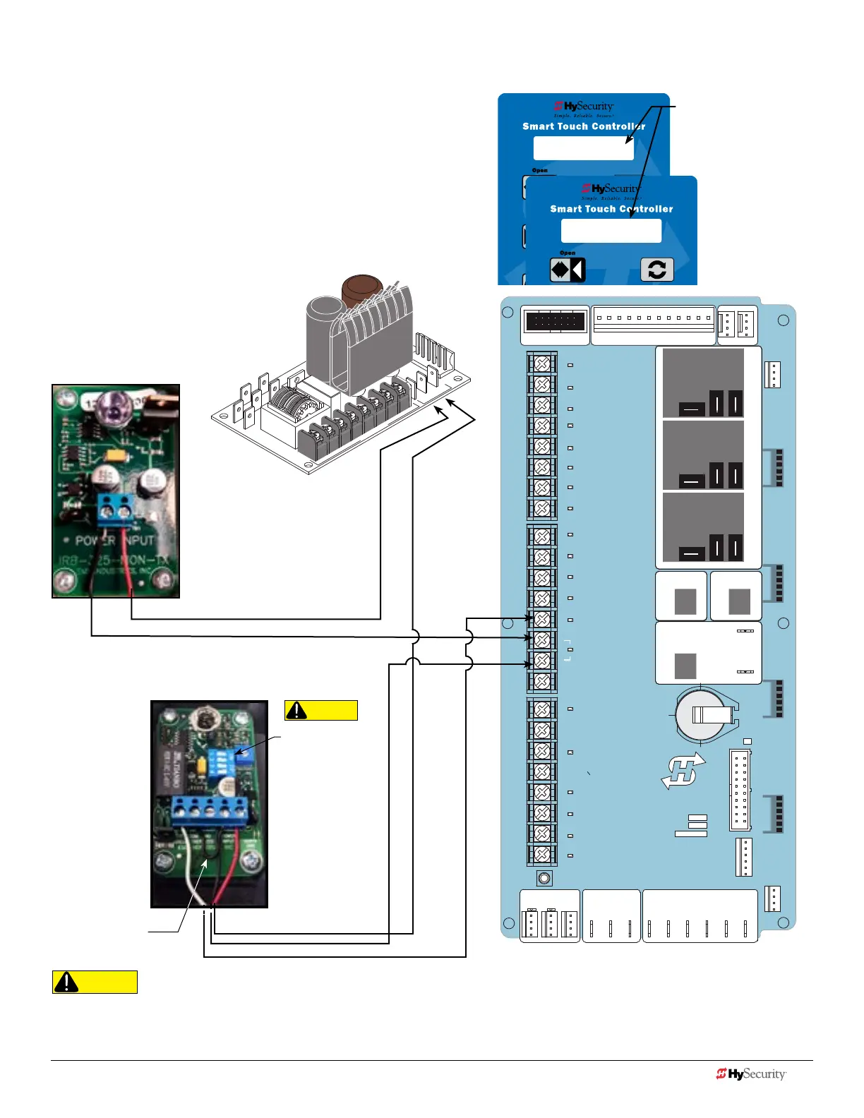
Smart toucH: pHoto eye tHru beam (emX Irb mon)
STOP BUTTON
OPEN BUTTON
CLOSE BUTTON
REMOTE OPEN AND
RADIO CONTROL
OPEN/CLOSE
1
OPEN PARTIAL
INTERLOCK OPEN
TIME CLOCK OPEN
FREE EXIT DETECTOR
DISABLE EXIT DETECTOR
DISABLE CLOSE TIMER
INSIDE OBSTRUCTION
VEHICLE DETECTOR
OUTSIDE OBSTRUCTION
VEHICLE DETECTOR
SHADOW/RESET
VEHICLE DETECTOR
SENSOR 1
SENSOR
COM
DO NOT USE
SENSOR 2
DO NOT USE
SENSOR 3
DO NOT USE
CHARGER
AC LOSS
LOCK INTERLOCK
EMERG CLOSE
FIRE DEPT OPEN
2
3
4
5
6
7
8
9
10
11
12
14
15
16
17
18
19
20
21
22
23
24
Smart Touch Controller
LIMIT DUAL GATE
RADIO OPTIONS
DRIVE
POWER
RS485
MOTOR USER 1
USER 2
USER 3
VEHICLE DETECTORVEHICLE DETECTORVEHICLE DETECTOR
STOP/BUZZER
FREE
EXIT
INSIDE
OBSTR
OUTSIDE
OBSTR
SHADOW
RESET
WIEGAND
HySecurity
COM
NO
MX000585
VERSION
S/N
RS232
DISPLAY
VEHICLE DETECTOR
COM COMA B
RPM
COMOPEN
S 1
+24V +24V
STATU S
LED
24V
A
C A
cce
s
s
or
y powe
r
+
24
V
D
C
S1 0
SENSOR #1 TYPE
S1 4 (EYE OPEN)
SENSOR #1 TYPE
Installer Menu showing
Sensor 1 set to Eye Open
(Option #4)*
EMX IRB MON Photo Eye
Receiver
Power Supply Board
EMX IRB MON Photo Eye
Transmitter
+24V
+24V
NC Relay
COMMON / NEG. to SENSOR COM
Jumper POWER
INPUT - 24V to COM
COMMON / NEG. to SENSOR COM
CAUTION
Set DIP Switches
1 = OFF
2 = OFF
3 = OFF
4 = ON
CAUTION
DIP switches must be set as shown otherwise the photo eye will not operate correctly. If you receive an Alert, "!ACTION BLOCKED"
"Photo Eye Open" PEO or "Photo Eye Close" PEC, take steps to align the photo eye. Refer to Photo Eye Alignment on page 12.
1. Connect photo eye wiring.
NOTE: Run a jumper between photo eye -24V (POWER
INPUT) and COM terminals on the Receiver.
2. Turn ON power.
3. Access the Installer Menu and congure SENSOR setting
according to the entrapment area that the photo eye is
monitoring. Refer to table on page 10.
*NOTE: Make sure whichever wired input used (SENSOR 1, 2, or 3) is the
same Sensor # congured through the Installer Menu.
26 D0726 Rev. J UL 325 - 2016 HySecurity Monitored Sensors © 2016 www.hysecurity.com
www.hysecurity.com © 2016 Quick Start D0726 Rev. J 27