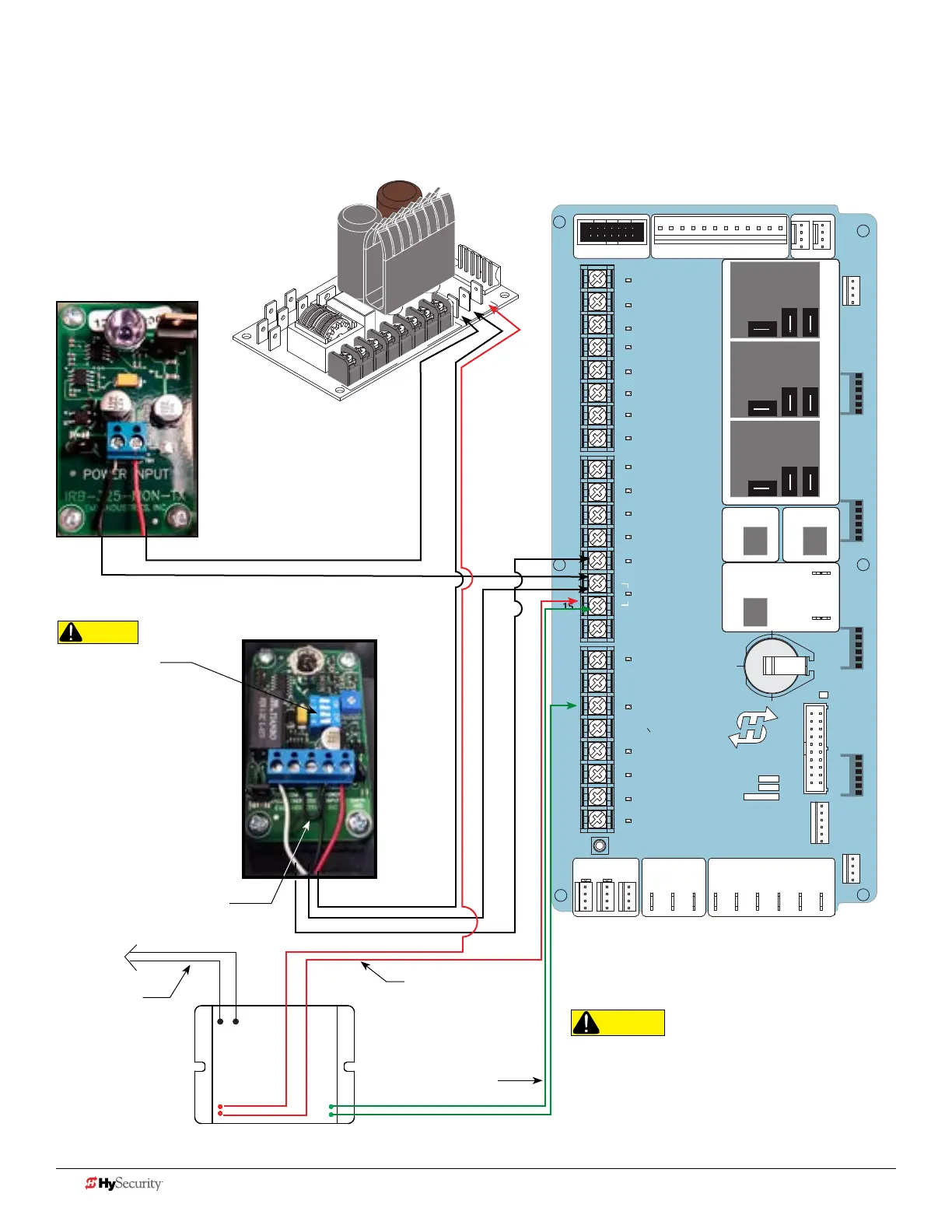
Smart toucH: wIred edGe wItH Gem-104 & pHoto eye
The wiring diagram illustrates a wired edge sensor with GEM-104 interface module and a photo eye connection. An
example of the connections for an Edge sensor and a Photo Eye and the Installer Menu settings for the Smart Touch
Controller (STC) are shown in Diagram 1 and Diagram 2 on 19 and 20.
For photo eye alignment, refer to
page 12.
STOP BUTTON
OPEN BUTTON
CLOSE BUTTON
REMOTE OPEN AND
RADIO CONTROL
OPEN/CLOSE
1
OPEN PARTIAL
INTERLOCK OPEN
TIME CLOCK OPEN
FREE EXIT DETECTOR
DISABLE EXIT DETECTOR
DISABLE CLOSE TIMER
INSIDE OBSTRUCTION
VEHICLE DETECTOR
OUTSIDE OBSTRUCTION
VEHICLE DETECTOR
SHADOW/RESET
VEHICLE DETECTOR
SENSOR 1
SENSOR
COM
DO NOT USE
SENSOR 2
DO NOT USE
SENSOR 3
DO NOT USE
CHARGER
AC LOSS
LOCK INTERLOCK
EMERG CLOSE
FIRE DEPT OPEN
2
3
4
5
6
7
8
9
10
11
12
14
15
16
17
18
19
20
21
22
23
24
Smart Touch Controller
LIMIT DUAL GATE
RADIO OPTIONS
DRIVE
POWER
RS485
MOTOR USER 1
USER 2
USER 3
VEHICLE DETECTORVEHICLE DETECTORVEHICLE DETECTOR
STOP/BUZZER
FREE
EXIT
INSIDE
OBSTR
OUTSIDE
OBSTR
SHADOW
RESET
WIEGAND
HySecurity
COM
NO
MX000585
VERSION
S/N
RS232
DISPLAY
VEHICLE DETECTOR
COM COMA B
RPM
COMOPEN
S 1
+24V +24V
STATU S
LED
24V
A
C A
cce
s
s
or
y powe
r
+
24
V
D
C
EMX IRB MON Photo Eye
Receiver
Power Supply Board
EMX IRB MON Photo Eye
Transmitter
+24V
+24V
NC Relay
COMMON / NEG. to SENSOR COM
Jumper POWER INPUT - 24V
to COM
COMMON / NEG. to SENSOR COM
B W
GEM: Red Wires
NOTE: Drawing is not to scale.
Combination of D0711 and D0712, Rev. A
*Green output wire can attach to
any SENSOR input.
GEM Black &
White Wires
GEM +24V
NOTE: DIP switches must
be set as shown otherwise
the photo eye will not
operate correctly. For easy
photo eye alignment, refer
to page 12.
CAUTION
Set DIP Switches
1 = OFF
2 = OFF
3 = OFF
4 = ON
CAUTION
All external entrapment protection sensors must be
NC sensor outputs and wired to the SENSOR COM
terminal for monitoring and powering purposes.
The sensor becomes actively powered when the
gate operator's motor runs.
32 D0726 Rev. J UL 325 - 2016 HySecurity Monitored Sensors © 2016 www.hysecurity.com
GEM:
Green Wires*
*NOTE: For 2
channel capabilities,
See Smart Touch:
2 CH Wired Edge
with GEM-204 on
page 34..