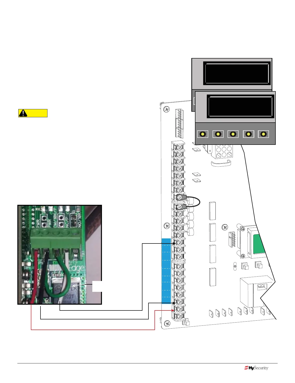
Smart dc: pHoto eye / refLectI-Guard (rG-r)
1. Turn OFF AC power.
2. Connect photo eye wiring.
NOTE: Run a jumper between photo eye -24V and CM terminals.
3. Turn ON power.
NOTE: Make sure both AC & DC switches are ON and the red battery
wire is plugged in.
4. Access the Installer Menu. Congure SENSOR
setting accordingly. For example, Eye Close,
Eye Open, or Eye Both.
Connect NC relay
wire to SENSOR 1,
2, or 3.
Reflecti-GUARD Photo Eye
COMMON / NEG. to SENSOR COM
+24V
NOTE: If you receive an Alert, "!ACTION BLOCKED"
"Photo Eye Open" PEO or "Photo Eye Close" PEC, take
steps to align the photo eye. Refer to Photo Eye
Alignment on page 12.
CAUTION
All external entrapment protection sensors must be NC sensor
outputs and wired to the SENSOR COM terminal for monitoring
and powering purposes. The sensor becomes actively powered
when the gate operator receives a run command.
COM
COM
COM
COM
COM
COM
COM
COM
STOP
OPEN
RADIO
CLOSE
OPEN
OPEN
PARTIAL
OPEN
EYE
EXIT
LOOP
EXIT
LOOP
LOOP
LOOP
EDGE
EYE
COM
+ 24 V
EMERG
OPEN
SHOW
LEDs
S
1
+
24V
OP
EN
C
O
M
D
U
AL
G
A
T
E
C
O
M
A
B
U
S
E
R2
C
O
M
N
O
D
C
USER RELAY 1
Electro-mechanical
24VDC
24VDC
12VDC
12VDC
SENSOR 2
SENSOR 3
SENSOR 1
SENSOR
COM
EXIT
LOOP
BLOCK
EXIT
CENTER
LOOP
IN OBS
LOOP
OUT OBS
LOOP
11
10
9
8
7
6
5
4
3
2
1
S2 0
SENSOR #2 TYPE
OPEN
CLOSE
STOP
MENU
RESET
PREV
NEXT
SELECT
S2 2 (EYE CLOSE)
SENSOR #2 TYPE
OPEN
CLOSE
STOP
MENU
RESET
PREV
NEXT
SELECT
Installer Menu Settings
Jumper, PWR -24V to
relay CM
40 D0726 Rev. J UL 325 - 2016 HySecurity Monitored Sensors © 2016 www.hysecurity.com
www.hysecurity.com © 2016 Quick Start D0726 Rev. J 41