wHat tHe InStaLLer needS to do
All HySecurity gate operators indicating a manufacturing date of 2016 (or later) in the serial number, will have the Build Year set to 2.
A Build Year of 2 (BY 2) indicates that your gate operator is prepared to monitor for external entrapment protection sensors. The Build
Year setting appears in the system scroll on the gate operator display. The gate operator will not automatically cycle the gate unless
an indication that the appropriate number of external entrapment protection sensors are connected and operational.
The normally closed (NC) entrapment protection sensors wired to the Controller's SENSOR inputs are monitored using
HySecurity software. Prompts appear in the display requesting specic congurations based on the gate operator type.
Table 5 illustrates what options are available for the HySecurity Controller's congurable inputs.
SENSOR 1 SENSOR 2 SENSOR 3 SENSOR COM
Assess Your Gate Site.
Design your gate installation so entrapment zones are kept to
a minimum, and then install your HySecurity gate operator.
Install NC sensors.
Install NC contact and non-contact
sensors (edge sensors and photo
eyes) for all potential entrapment zones. HySecurity gates monitor normally
closed (NC) sensors. Wire your NC sensors to SENSOR input terminals (SENSOR 1,
SENSOR 2, or SENSOR 3) on the Smart Touch or Smart DC Controllers. The SENSOR
inputs are interchangeable and congurable. For example, it doesn't matter whether you
wire a normally closed photo eye sensor or edge sensor to the SENSOR 1, 2, or 3 input.
CAUTION
All external entrapment protection sensors must be NC sensor outputs and wired to
the SENSOR COM terminal for monitoring and powering purposes. The sensor becomes
actively powered when the gate operator receives a run command.
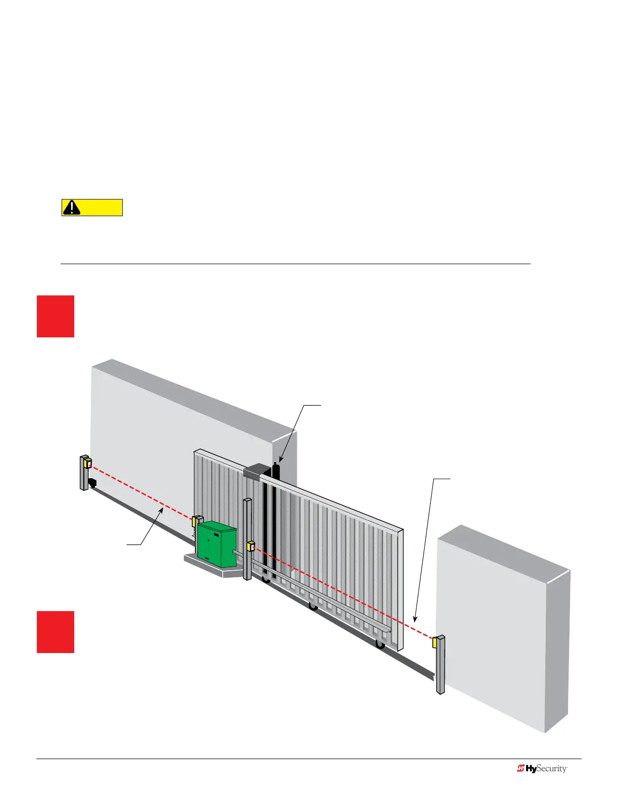
Photo eye thru-beam
protecting Trailing End (EYE
OPEN)
Photo eye thru beam protecting
Leading End
(EYE CLOSE)
Draw-in zone
Edge sensor (protecting open direction)
(EDGE OPEN)
NOTE: When installing wired edge sensors, the WIRED EDGE edge must be connected to an interface module
that produces an NC output. Refer to Table on page 6. Wireless edge sensors require no interface module.
8 D0726 Rev. J UL 325 - 2016 HySecurity Monitored Sensors © 2016 www.hysecurity.com
www.hysecurity.com © 2016 Quick Start D0726 Rev. J 9