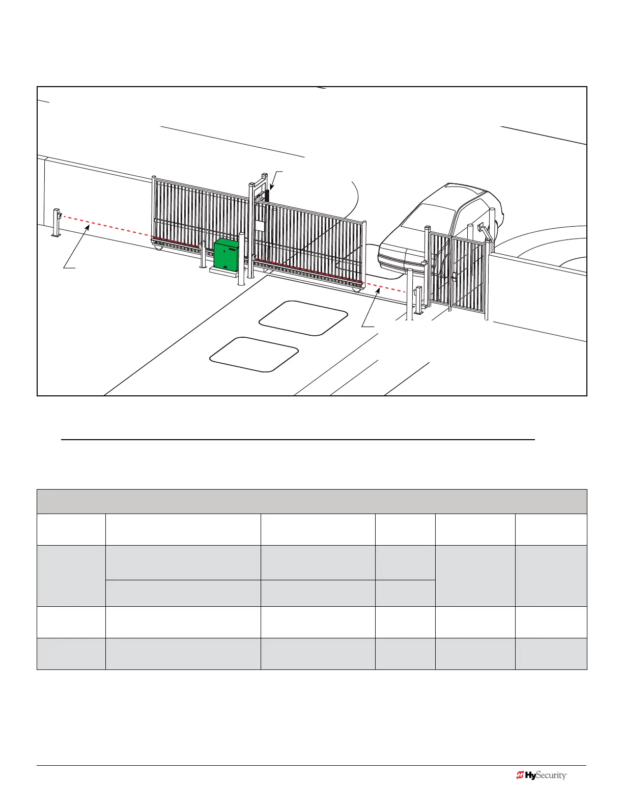
dIaGram 1: typIcaL SLIde Gate SIte aSSeSSment
NOTICE: HySecurity slide gates are equipped with a Type A inherent entrapment sensor (IES) that complies with
UL 325. Any impediment to gate travel causes the gate to stop and reverse.
Monitored external entrapment protection sensors, which can be used in this site scenario and are compatible with
HySecurity slide gates, appear in the following chart. For a full list, refer to page 6.
EXAMPLE: External Entrapment Protection Sensors: Normally Close Contact, Compatible with HySecurity Gate Operators
P/N 2016 Monitored Sensors Sensor Type Output Manufacturer
UL 325
Recognized
MX3981
MX3983
Wired Gate Edge Sensor
MGR20-2U-05-T2, Round
Wraparound edge
(5 ft for 2" round post)
10K
Resistor
Miller Edge Type B2
Gate Edge Module (GEM -104) Edge Interface Module
Normally
Closed
MX3990 IRB-MON (Dist.~ 65 ft)t Thru-beam photo eye
Normally
Closed
EMX Industries Type B1
MX3990 IRB-MON (Dist.~ 65 ft) Thru-beam photo eye
Normally
Closed
EMX Industries Type B1
A minimum of one monitored external entrapment protection sensor, in addition to the slide gate operator’s inherent
sensor, is required before enabling momentary control activation. However, if there is a risk of entrapment in both
directions of gate travel, then both directions of travel must be protected by an external sensor.
NOTE: At minimum, external entrapment protection sensors must be installed wherever potential for entrapment exists during gate
movement. Note that every site is different. All potential entrapment zones should be protected with contact or non-contact
sensors. HySecurity gate operators detect NC output sensors and monitor them to comply with UL 325 Standard of Safety.
NOTE: This scenario shows a possible conguration with the minimum recommended external entrapment protection sensors.
Other sensor congurations are valid. Each gate site is different. It is the installer's responsibility to assess and protect all
entrapment zones.
Drawing is not to scale
Photo eye thru-beam
protecting Trailing End of
gate (Open direction of
travel)
Photo eye thru beam
protecting Leading End of
gate (Close direction of travel)
Edge sensor
(protecting open
direction) Draw-in
zones
18 D0726 Rev. J UL 325 - 2016 HySecurity Monitored Sensors © 2016 www.hysecurity.com
www.hysecurity.com © 2016 Quick Start D0726 Rev. J 19