COM
COM
COM
COM
COM
COM
COM
COM
STOP
OPEN
RADIO
CLOSE
OPEN
OPEN
PARTIAL
OPEN
EYE
EXIT
LOOP
EXIT
LOOP
LOOP
LOOP
EDGE
EYE
COM
+ 24 V
EMERG
OPEN
SHOW
LEDs
S
1
+
24V
OP
EN
C
O
M
D
U
AL
G
A
T
E
C
O
M
A
B
U
S
E
R2
C
O
M
N
O
D
C
USER RELAY 1
Electro-mechanical
24VDC
24VDC
12VDC
12VDC
SENSOR 2
SENSOR 3
SENSOR 1
SENSOR
COM
EXIT
LOOP
BLOCK
EXIT
CENTER
LOOP
IN OBS
LOOP
OUT OBS
LOOP
11
10
9
8
7
6
5
4
3
2
1
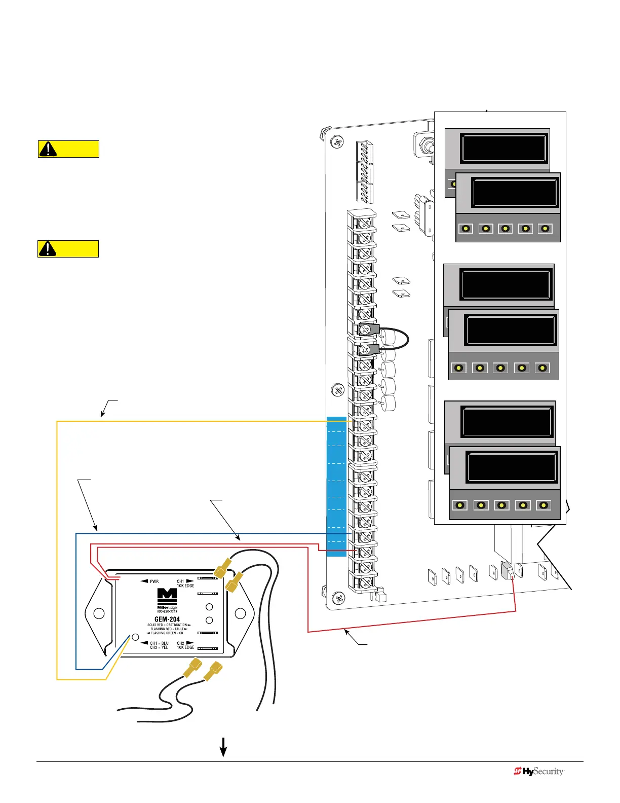
Smart dc: 2 cH wIred edGe wItH Gem-204
The wiring diagram illustrates a WIRED edge receiver connected to the
SDC controller via the 2 channel GEM-204.
NOTE: Turn OFF AC power before connecting sensor wires to Smart DC.
CAUTION
Connect all contact and non-contact sensors to same power
source. Example, Do NOT connect photo eyes to +24VDC
and gate edges to +12VDC. Incompatible electricity ow. A
FAULT 2 will appear.
CAUTION
All external entrapment protection sensors must be NC
sensor outputs and wired to the SENSOR COM terminal for
monitoring and powering purposes. The sensor becomes
actively powered when the gate operator receives a run
command.
Red wire
Power +24V
Channel wires to 10k Edge
Red wire SENSOR COM
The sensors do not become active
until the motor runs.
NOTE: Red wires are not polarity
sensitive.
NOTE: In 2012, location of
pins changed. Older boards
show pins swapped.
Yellow wire
SENSOR connection for CH 2
Blue wire
SENSOR Connection for CH 1
Conguring SENSOR 3
S1 0
SENSOR #1 TYPE
OPEN
CLOSE
STOP
MENU
RESET
PREV
PREV
NEXT
SELECT
S1 5 (EDGE OPEN)
SENSOR #1 TYPE
OPEN
CLOSE
STOP
MENU
RESET
PREV
NEXT
SELECT
S2 0
SENSOR #2 TYPE
OPEN
CLOSE
STOP
MENU
RESET
PREV
NEXT
SELECT
S2 3 (EDGE CLOS)
SENSOR #2 TYPE
OPEN
CLOSE
STOP
MENU
RESET
S3 0
SENSOR #3 TYPE
OPEN
CLOSE
STOP
MENU
RESET
PREV
NEXT
SELECT
S3 1 (NOT USED)
SENSOR #3 TYPE
OPEN
CLOSE
STOP
MENU
RESET
PREV
NEXT
SELECT
Conguring SENSOR 2
Conguring SENSOR 1
Installer Menu Settings
44 D0726 Rev. J UL 325 - 2016 HySecurity Monitored Sensors © 2016 www.hysecurity.com
www.hysecurity.com © 2016 Quick Start D0726 Rev. J 45