Wiring HySecurity Sensors: Smart DC
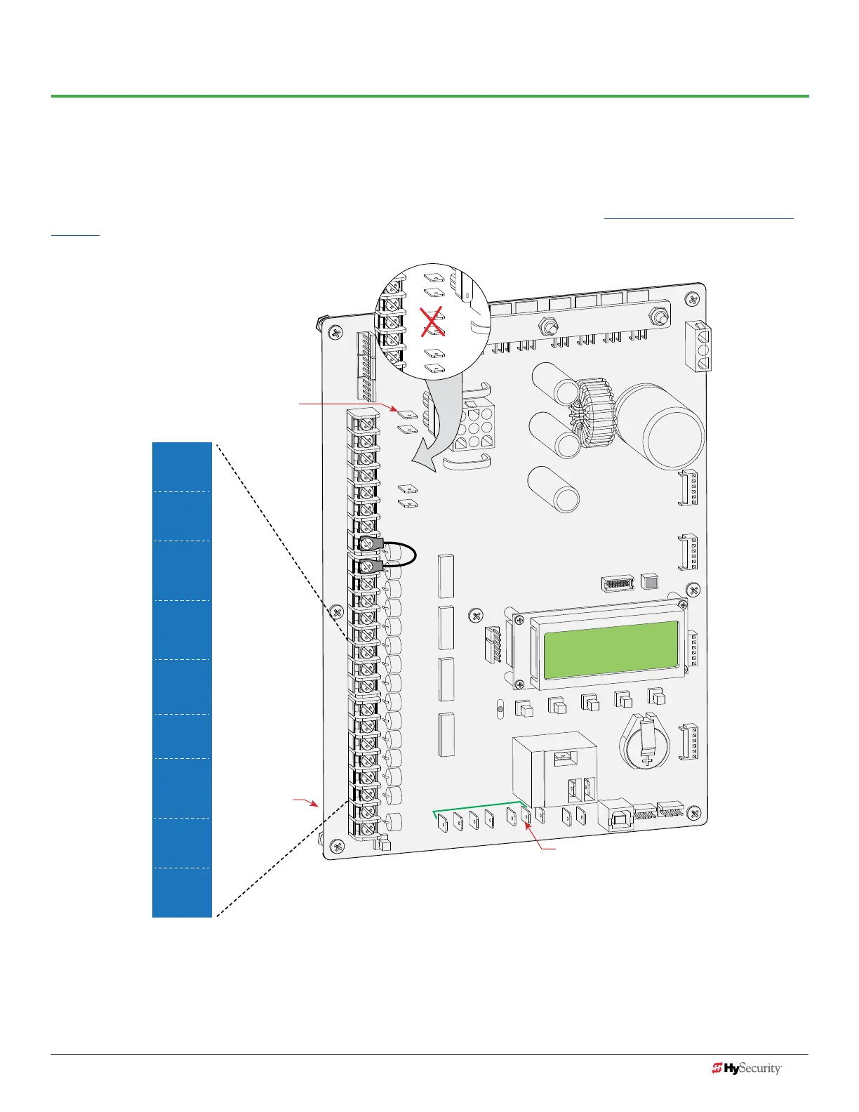
Wiring diagrams are provided on the following pages. The diagrams illustrate how to connect sensors and program
the gate operator. HySecurity Smart DC gate operators can monitor entrapment protection sensors per UL 325 - 2015
Standard of Safety using software version h5.50 (or higher).
The site designer or installer must determine which external entrapment protection sensors will be installed with the gate
operator to create a UL 325 compliant installation site. For additional information, review Gate Safety on the HySecurity
website.
COM
COM
COM
COM
COM
COM
COM
COM
STOP
OPEN
RADIO
CLOSE
OPEN
OPEN
PARTIAL
EXIT
LOOP
BLOCK
EXIT
IN OBS
LOOP
OUT OBS
LOOP
CENTER
LOOP
EDGE
EYE
COM
+ 24 V
EMERG
OPEN
SHOW
LEDs
R
A
D
I
O
OPT
IO
N
S
S
1
+
24V
OP
EN
C
O
M
D
U
AL
G
A
T
E
C
O
M
A
B
U
S
E
R2
C
O
M
N
O
D
C
USER RELAY 1
Electro-mechanical
24VDC
24VDC
12VDC
12VDC
24VDC
24VDC
24VAC
24VAC
12VDC
12VDC
R
S
-
4
8
5
U
S
B
SENSOR 2
SENSOR 3
SENSOR 1
SENSOR
COM
EXIT
LOOP
BLOCK
EXIT
CENTER
LOOP
IN OBS
LOOP
OUT OBS
LOOP
EYE
CLOSE
EYE
OPEN
NOTE: In 2012, location
of pins changed. Older
boards show pins
swapped.
Power: +24VDC
connections
Power: +24VDC connections
Power: +24VDC
connections
34 D0726 Rev. J UL 325 - 2016 HySecurity Monitored Sensors © 2016 www.hysecurity.com
www.hysecurity.com © 2016 Quick Start D0726 Rev. J 35