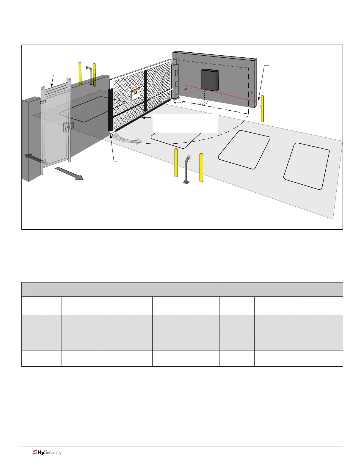
dIaGram 2: typIcaL SwInG Gate SIte aSSeSSment
WARNING
Moving Gate Can Cause
Serious Injury or Death
KEEP CLEAR! Gate may move at any me without
prior warning.
Do not let children operate the gate or play in
the gate area.
This entrance is for vehicles only. All pedestrians
must use a separate entrance.
Read the owner’s manual and safety instrucons.
Reective Photo Eye to
protect potential
Entrapment Zone
which exists if gate
comes within 16 inches
of a rigid object.
Wraparound edge sensor
for potential Entrapment
Zone along base of gate.
Wraparound *
edge sensor on the
Leading End.
Drawing is not to scale.
Pedestrian
gate
NOTICE: HySecurity swing gates are equipped with a Type A inherent entrapment sensor (IES) that complies with
UL 325. Any impediment to gate travel causes the gate to stop and reverse.
Monitored external entrapment protection sensors, which can be used in this site scenario and are compatible with
HySecurity swing gates, appear in the following chart. *For a full list, refer to page 6.
Example: External Entrapment Protection Sensors: Normally Close Contact, Compatible with HySecurity Gate Operators*
P/N 2016 Monitored Sensors Sensor Type Output Manufacturer
UL 325
Recognized
MX3981
MX3983
Wired Gate Edge Sensor
MGR20-2U-05-T2, Round
Wraparound edge
(5 ft for 2" round post)
10K
Resistor
Miller Edge Type B2
Gate Edge Module (GEM -104) Edge Interface Module
Normally
Closed
MX3985 Reecti-Guard (RG-R) Photo eye, reective
Normally
Closed
Miller Edge Type B1
A minimum of one monitored external entrapment protection sensor, in addition to the swing gate operator’s inherent
sensor, is required before enabling momentary control activation. Installers may decide both the type and location of the
one required entrapment protection sensor to protect either the open direction, the close direction or both directions of
swing gate travel. However, if there is a risk of entrapment in both directions of gate travel, then both directions of travel
must be protected by an external sensor.
NOTE: If a photo eye open is the only external entrapment protection sensor connected to a swing gate, it's application will require
a constant push button hold close for the swing gate to operate. HySecurity gate operators detect NC output sensors and monitor
them to comply with UL 325 Standard of Safety. Understand that UL 325 conveys the minimum standard of safety. Installers must
assess each specic gate design and site and install external entrapment protection sensors to guard all potential entrapment zones.
* If gate does not accommodate 2" wraparound edge
sensor, two standard channel mount edge sensors may
need to be used.
NOTE: If the bottom edge of a swing gate is greater than 6 inches (152 mm) above the ground at
any point in its arc of travel, one or more contact sensors shall be located on the bottom edge.
20 D0726 Rev. J UL 325 - 2016 HySecurity Monitored Sensors © 2016 www.hysecurity.com