Chapter 5 I/O Parameter
120
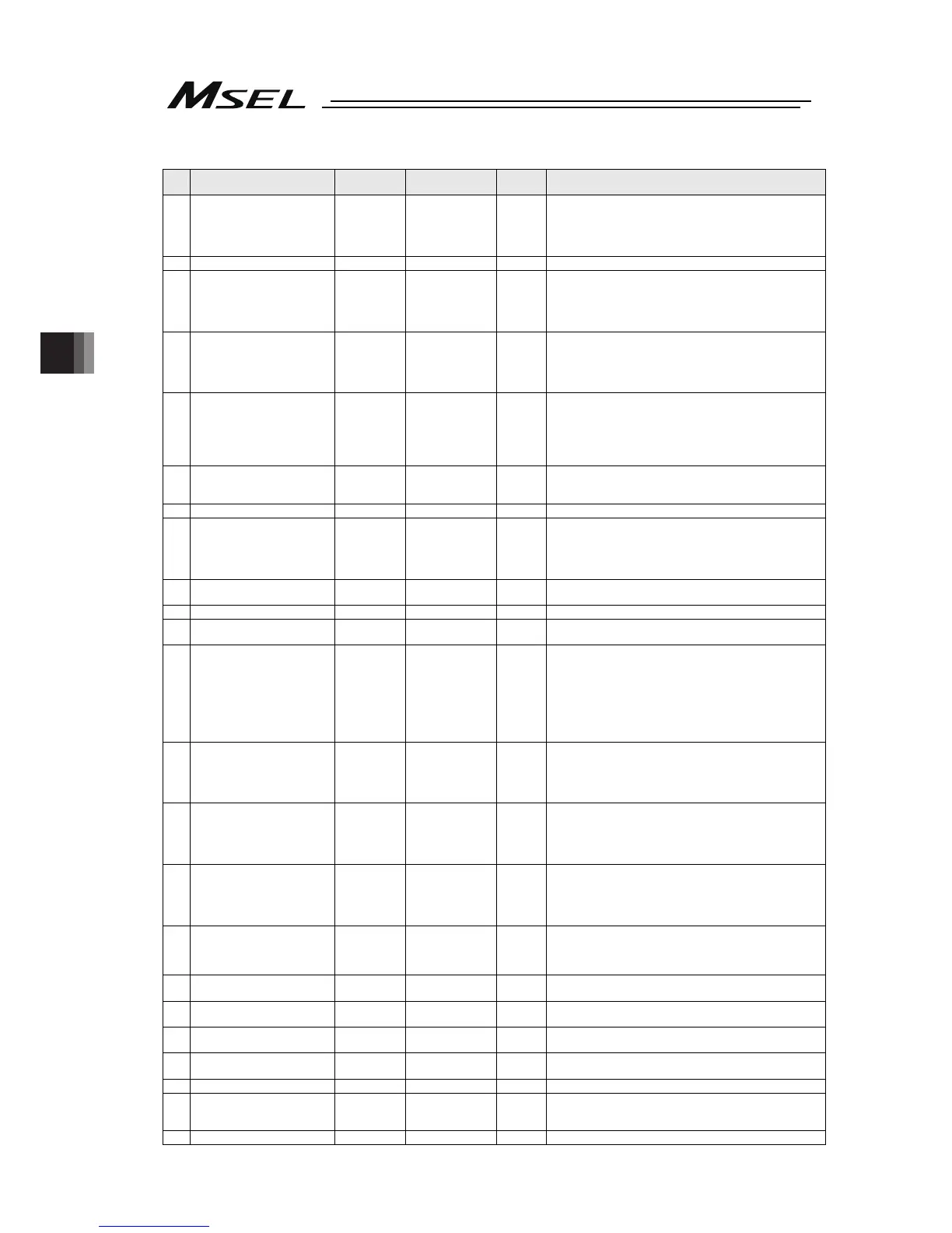
Axis-Specific Parameters
No. Parameter name
Default value
(Reference)
Input range Unit Remarks
17
Initial home sensor escape
velocity at power recovery
10
(PC/PG/
PCF/PGF),
10, 10, 10, 10
(PCX/PGX)
1 ~ 100 mm/sec
18 System reservation 100 1 ~ 500 mm/sec
19
End search speed at home
return
20
(PC/PG/
PCF/PGF),
12, 12, 10, 20
(PCX/PGX)
1 ~ 100 mm/sec
20
Phase-Z search speed at
home return
3
(PC/PG/
PCF/PGF),
3, 3, 3, 3
(PCX/PGX)
1 ~ 540 mm/sec
Exercise caution, since limitations apply depending on the
read/encoder pulse count.
21
Offset travel distance at home
return
1000
(PC/PG/
PCF/PGF),
3000, 3000,
3000, 1000
(PCX/PGX)
-99999999 ~
99999999
0.001mm
Offset travel distance from the ideal phase-Z position
(Positive value = Applied in the direction of moving away
from the end)
22
Allowable value for phase Z
position error check during
home return
0 0 ~ 99999999 0.001mm
Allowable actual minimum distance between the end
(Mechanical or LS) and phase Z when a rotary encoder is
used.
23 System reservation 1 1 ~ 8
24
Push stop check time at home
return
700
(PC/PG/
PCF/PGF)
1500
(PCX/PGX)
1 ~ 5000 msec Used to confirm pusing action at the time of home return.
25
Push stop check time at
positioning
500 1 ~ 5000 msec
Used to confirm pusing action according to the PUSH
command.
26 System reservation 0 0 ~ 99999
27
System reservation
(Change prohibited)
5000 1 ~ 99999
28
MAX operational velocity of
each axis
(PC/PG/PCF/PGF type)
MAX PTP velocity (SCARA axes)
MAX operational velocity of
each axis (Linear sliding axes)
(PCX/PGX type)
300
(PC/PG/
PCF/PGF)
161, 266,
189, 500
(PCX/PGX)
1 ~ 9999
mm/s
deg/s
* (PG/PGX type) Maximum SCARA CP velocity is set in All
Axes Parameter No. 21
29
VLMX speed
(PC/PG/PCF/PGF type)
Linear sliding axis VLMX
speed (PCX/PGX type)
300
(PC/PG/
PCF/PGF)
800
(PCX/PGX)
1 ~ 9999 mm/s
During VLMX operation, the maximum operating speed of
each axis or VLMX speed, whichever is lower, is used as
the maximum speed of the applicable axis.
* Linear sliding axes of only
30 Servo ON check time 20 0 ~ 5000 msec
Brake equipped: Time after receiving a servo-ON start
response until start of brake unlocking
Brake not equipped: Time after receiving a servo ON start
response until transition to an
operation-enabled status
31
Offset travel speed at home
return
3
(PC/PG/
PCF/PGF)
12, 12, 10, 3
(PCX/PGX)
1 ~ 500 mm/sec
32
Actual distance between
phase Z and end
0 -1 ~99999 0.001mm
Absolute distance from the end (Mechanical or LS).
Obtained automatically if the distance is a negative value.
When multiple actuators are combined, it is recommended
to write the flash ROM after automatic acquisition.
33
Ideal distance between phase
Z and end
0 0 ~ 99999 0.001mm Absolute distance from the end (Mechanical or LS).
34 Brake equipment specification 0 0 ~ 1
0: Not equipped
1: Equipped
35 Brake unlock check time 10 0 ~ 3000 msec
Time after receiving a brake-unlock start response until
transition to an operation-enabled status
36 Brake lock check time 10 0 ~ 1000 msec
Time after receiving a brake-lock start response until start of
servo OFF
37 System reservation 0 0 ~ 1
38 Encoder ABS / INC type 0 0 ~ 2
0: INC
1: System reservation
2: ABS (Battery-less ABS specification)
39 System reservation 1 0 ~ 1

 Loading...


