Chapter 7 Appendix
208
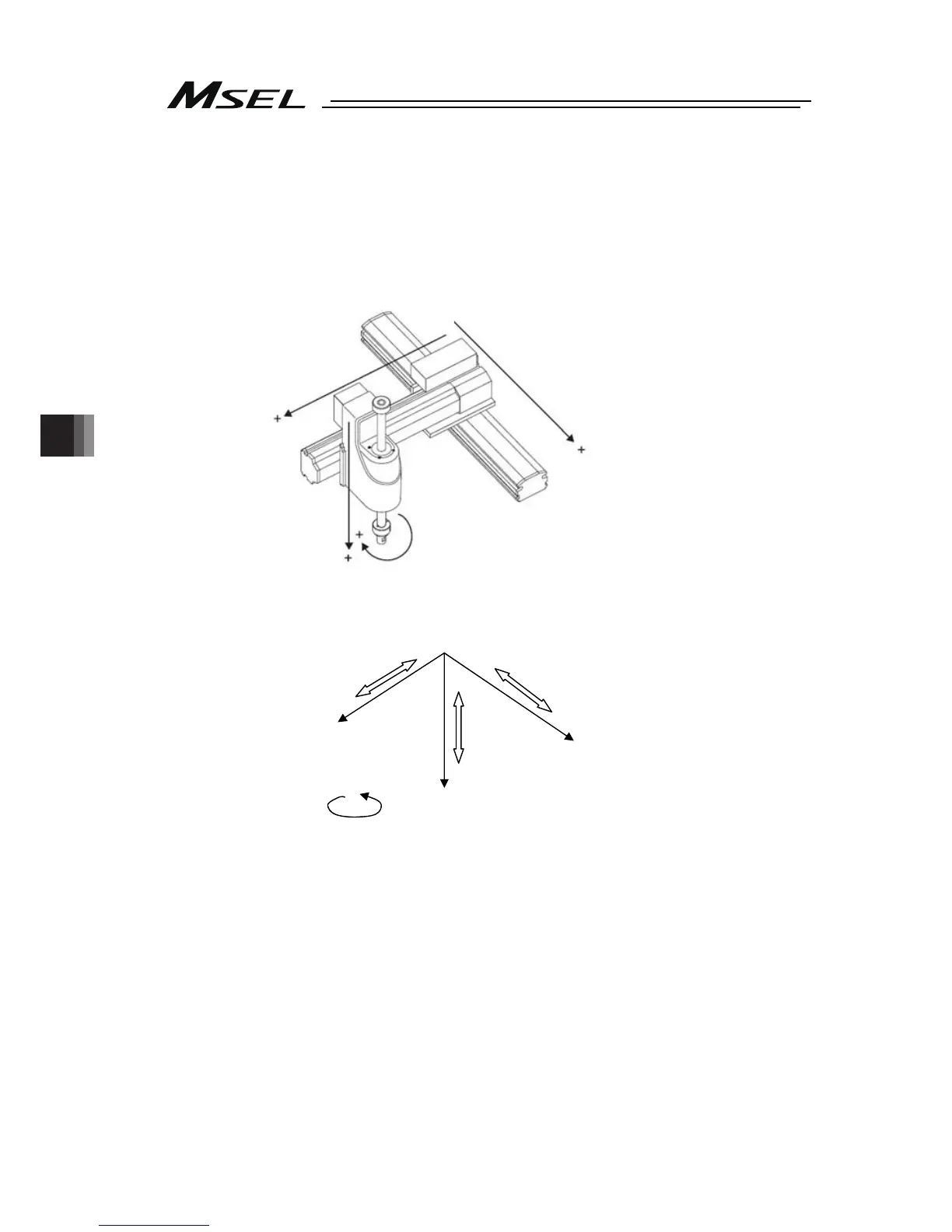
7.4.2 Base Coordinate System
It is the coordinate system to indicate the position of the datum point for tool installation
against the work piece mount face. Work Coordinate System No. 0 (work coordinate system
offset 0) = Base Coordinate System. X axis of Base Coordinate System is described as Xb, Y
axis as Yb, Z axis as Zb and R axis as Rb.
3rd axis (Zb-Axis)
(AXIS3)
2nd axis (Yb-Axis)
(AXIS2)
1st axis (Xb-Axis)
(AXIS1)
4th axis (Rb-Axis)
(AXIS4)
4th axis Rb-Axis)
(AXIS4)
1st axis (Xb-Axis)
(AXIS1)
3rd axis (Zb-Axis)
(AXIS3)
2nd axis (Yb-Axis)
(AXIS2)
-
+
0 (Home)
-
+
-
+

 Loading...


