Chapter 2 Wiring
40
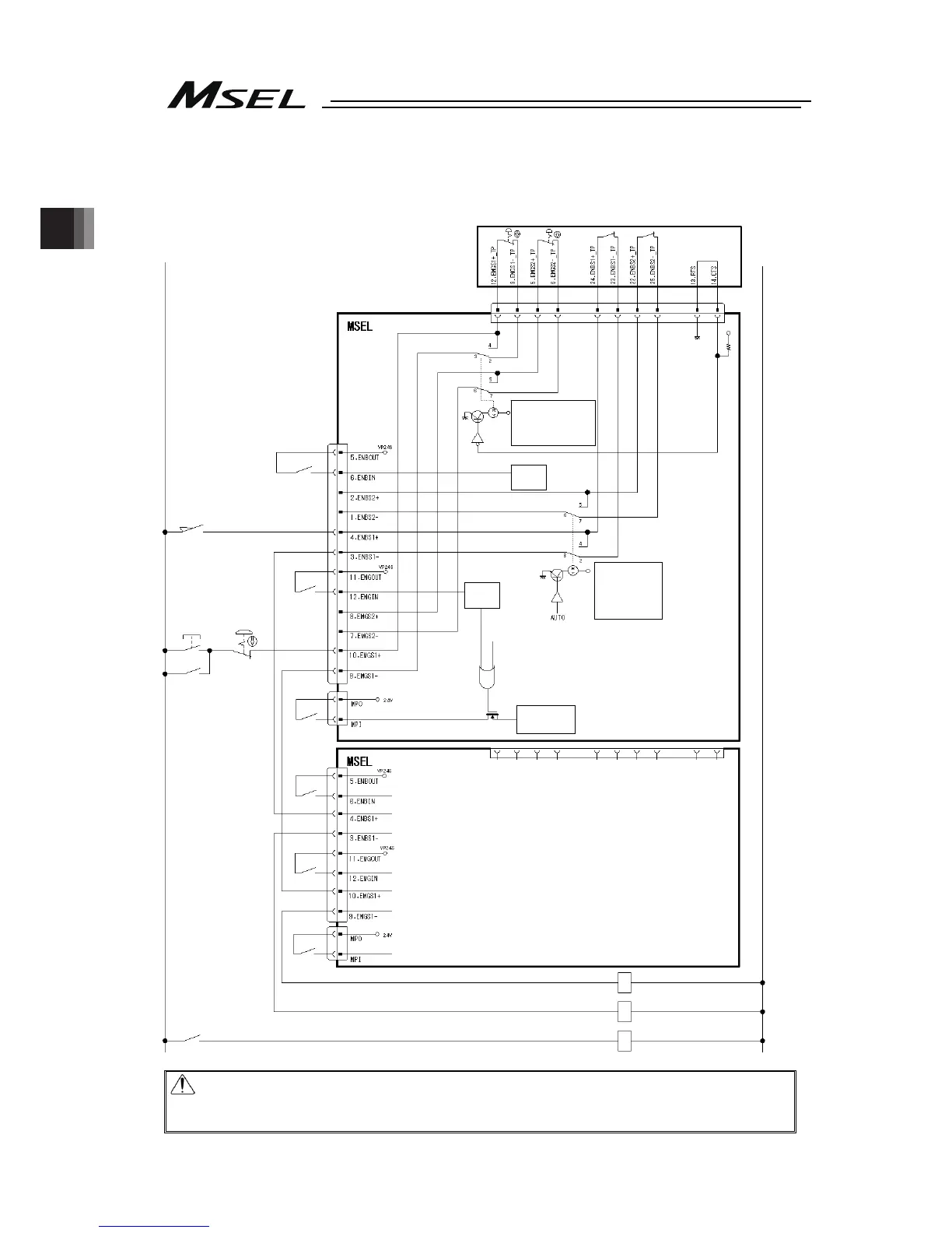
2.2.2 Emergency Stop and Enable Circuit (PC/PCF/PCX Type)
The following diagram shows the case when the teaching pendants emergency stop switch is
reflected on the machine’s emergency stop circuit design.
Caution: For PC/PCF/PCX type, the dead man’s switch on the teaching pendant is valid
in MANU Mode. The Emergency Stop Switch is always enabled regardless of
MANU/AUTO mode.
0V
Teaching pendant
24V
System I/O
Connector
Motor driving power supply
line connector
SIO Connector
CR1
CR2
Safety gate
CR1
MC1
Emergency
stop reset
switch
CR2
MC1
Emergency
stop switch
CR1
CR2
MC1CR1
Teaching pendant connected
2-3 and 6-7 short-circuited
Teaching pendant disconnected
3-4 and 5-6 short-circuited
MANU mode
2-3 and 6-7
short-circuited
AUTO mode
3-4 and 5-6
short-circuited
(Note 1)
(Note 2)
(Note 4)
(Note 3)
(Note 4)
(Note 5)
(Note 5)
Motor driving
circuit
ENB
Status
detection
EMB
Status
detection

 Loading...


