Chapter 7 Appendix
207
7.4 Cartesian Axis Coordinate Systems
It can be applicable to SEL program communication and IAI protocol communication features if
serial communication type (model code SE1: RS232C, SE2: RS485) is mounted to the extension
I/O.
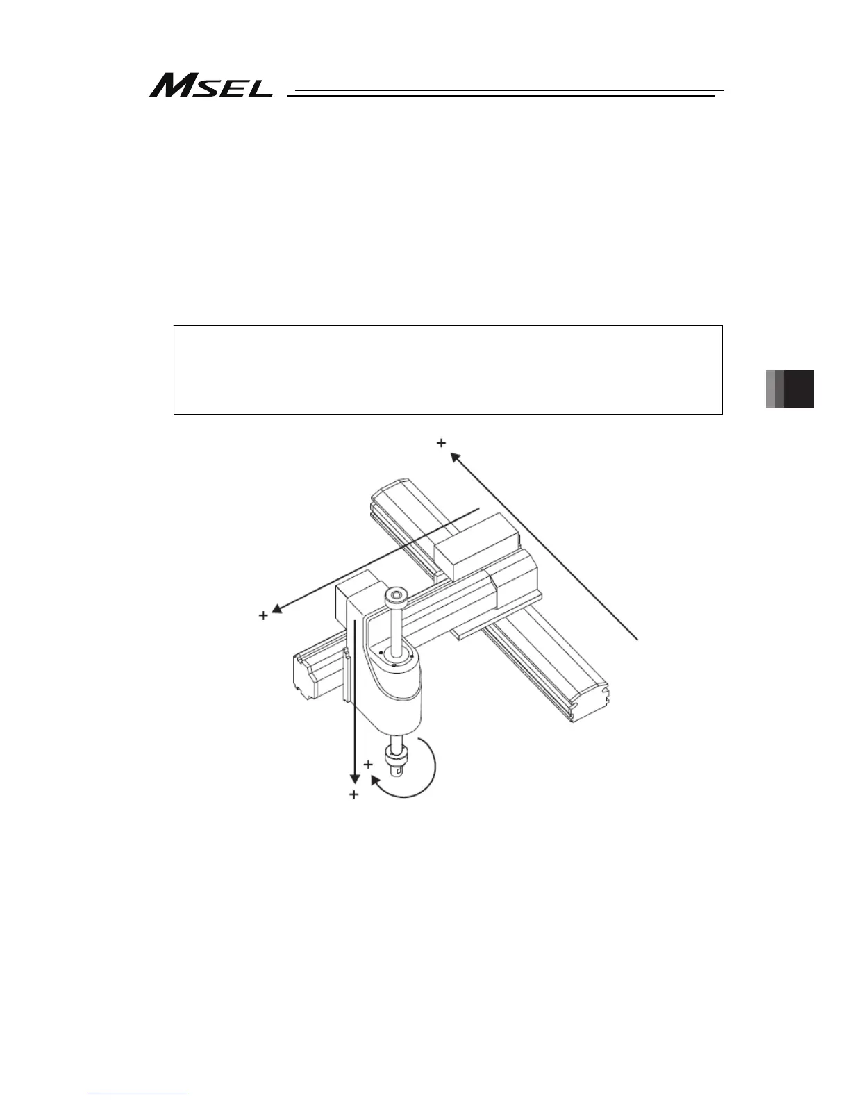
7.4.1 Coordinates for Coordinate System Definition Unit
The coordinate system for the coordinate system definition unit consists of four coordinate
axes at the maximum (X-axis, Y-axis, Z-axis and R-axis).
At this time, it should be premised that the physical axes applicable for each coordinate axis
satisfy the following conditions.
Figure : Example for orthogonal unit satisfying conditions above
・X-axis, Y-axis and Z-axis are laid orthogonally to each other.
・The center axis of rotary for the R-axis is laid orthogonally to XY plane. (It is parallel to
Z-axis if there is Z-axis.)
・A tool is attached on the R-axis if there is R-axis. (It should be premised that the tool
attachment datum point is on the R rotation axis.)
Y-Axis
X-Axis
Z-Axis
R-Axis

 Loading...


