Chapter 2 Wiring
56
The following pin numbers are connected with a short-circuiting cable at the delivery.
Pins 4 and 5
Pins 3 and 6
Pins 10 and 11
Pins 9 and 12
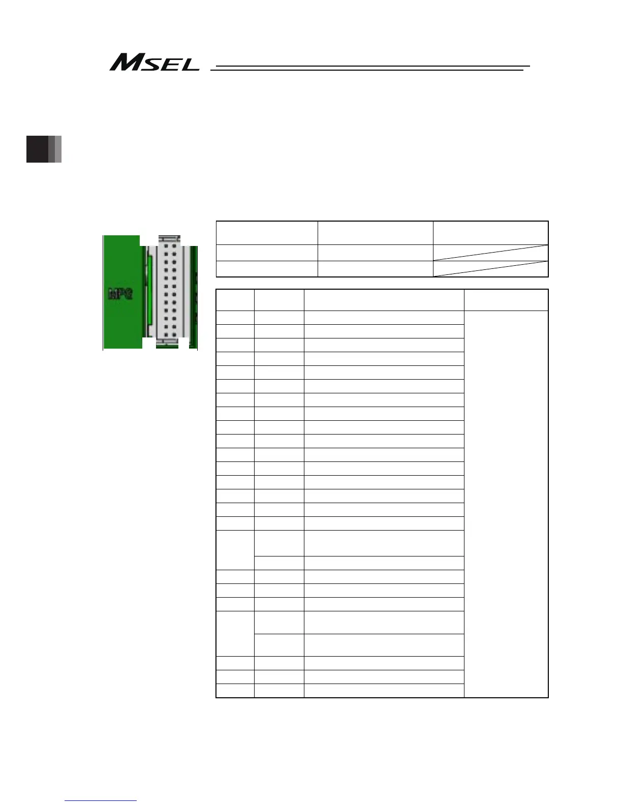
2.3.3 Wiring for Actuator
Connect the relay cables to the actuator connectors.
Check in the instruction manual of each actuator for the details of the relay cables.
Actuator Connection
Connector
Model Remarks
Cable side
PADP-24V-1-S
Controller side
S24B-PADSS-1
Note 1 The pin assignment of the connector that the high-thrust type axis
can be connected and that of the connector that all the other
types of axis can be connected are different from each other.
Pin No.
Signal
Name
Description
Applicable Wire
Diameter
1
A
Motor driving A-phase
2 VMM
Motor power
3
B
Motor driving B-phase
4 VMM
Motor power
5
/A
Motor driving /A-phase
6
/B
Motor driving /B-phase
7 LS +
Limit switch positive side
8 LS -
Limit switch negative side
9 BK +
Brake release positive side
10 BK -
Brake release negative side
11 ABS_SA Absolute encoder differential + input
12 ABS_SB Absolute encoder differential - input
13 A + Encoder A-phase differential + input
14 A - Encoder A-phase differential - input
15 B + Encoder B-phase differential + input
16 B - Encoder B-phase differential - input
5V
Encoder power supply
(except for high-thrust axis)
17
(Note 1)
NC Disconnected (High-thrust axis )
18 /PS
Encoder line driver enable output
19 GND
Ground
20 LSGND
Ground for limit switch
NC
Disconnected
(except for high-thrust axis)
21
(Note 1)
5V
Encoder power supply
(High-thrust axis)
22 NC Disconnected
23 NC Disconnected
24 FG Grounding
Cable dedicated for
IAI products
Front view of
connector on
controller side
1
2
23
24

 Loading...


