Chapter 1 Specications Check
27
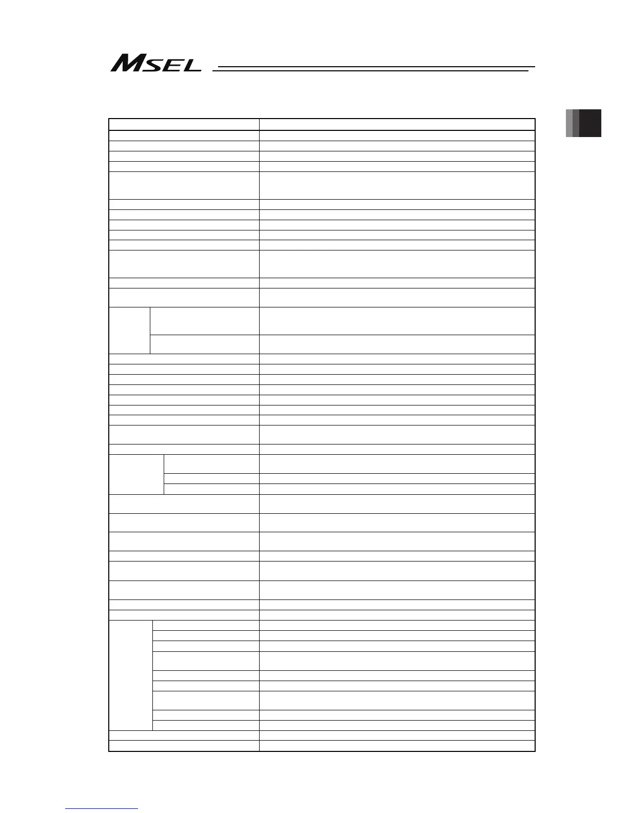
1.2 Basic Specifications
Specification Item
Number of Controlled Axes 1 axis to 4 axes (Total of RC axis or SCARA axis + RC axis is four axes max.)
Power Supply Voltage Single-phase 100V AC to 230V±10%
Power Current (typ value) 2.9A (100V AC), 1.4A (200V AC), 1.2A (230V)
Power Supply Frequency 50Hz/60Hz±5%
Rush Current (typ value)
(Note 1)
15A(100V AC), 30A(200V AC)
(Ambient Temp. 25degC, Measurement in one time of turn-ON: when no
repeating of ON/OFF)
Leakage Current
(Note 2)
0.75mA or less
Transient Power Cutoff Durability 20ms or more
Heat Generation 40W (100V AC), 35.2W (200V AC), 30.4W (230V AC)
PIO Power Supply
(Note 3)
DC24V±10% (Supplied from external equipment)
Motor Control System Weak field-magnet vector control
Applicable Encoder
(The resolution differs depending on the
actuator type)
Battery-less absolute encoder or Incremental encoder
resolution 800pulse/rev or 8192pulse/rev
Actuator Cable Length MAX. 20m (when simple absolute type is used Max.10m)
Serial Communication Interface (SIO port
or USB port)
Teaching tool dedicated connector (SIO ports and USB ports excluded)
(XSEL serial communication protocol (Format B))
(Standard / extension) PIO
24V DC general-purposed signal I/O (NPN / PNP selection)
Input 32 points max., output 32 points max. (Total of standard and extension)
Cable length MAX.10m
External
Interface
(Extension dedicated) Fieldbus
DeviceNet, CC-Link, PROFIBUS-DP, EtherNet/IP
(Note 4)
, EtherCAT,
PROFINET IO, RS232C, RS485
Data Setting and Input PC software or teaching pendant
Program Specification SEL Language
Max. Number of Program Steps 9999 steps
Max. Number of Positions 30000 position
Max. Number of Programs 255 program
Max. Number of Multitask Programs 16 program
Data Retention Memory Flash ROM and FeRAM
Clock Function
Retaining time after power turned OFF: approximately 10 days
Time for battery charge after the clock data is lost: approximately 100 hours
System I/O Emergency stop input, safety gate input
Drive-source cutoff method
Contact point for semiconductor (connect externally such as driving source cutoff
relay when required to comply with safety categories for PG/PGF/PGX types)
Emergency-stop input
b contact (normally closed) Input (internal power supply)
Safety Circuit
Configuration
Enable input
b contact (normally closed) Input (internal power supply)
Protective Functions
Motor over current, overload, encoder open circuit detection, soft limit over,
system abnormality, battery abnormality
Absolute Battery (when simple absolute
type is used)
AB-7
Protection Function Against Electric
Shock
Class I In case grounding conducted on ground terminal in addition to basic
insulation for electric shock proof.
Overvoltage Category Category II Voltage durability 2500V at less than 300V AC for input rating
Insulation Resistance
10MΩ or more (between power terminal and I/O terminal and also all external
terminals and case at the power supply of DC500V)
Insulation Strength
1500V AC for 1 min (between primary and PE)
3000V AC for 1 min (between primary and secondary)
Protection Conduction 10A 1.0V or less (for 10sec)
Cooling Method Forced air-cooling
Surrounding air temperature 0 to +40°C
Surrounding humidity
85% RH or less (non-condensing)
Surrounding environment
(Refer to the Item for the 1.6 Installation Environment).
Surrounding storage
temperature
-20 to 70C (Note) 0 to 40C for absolute battery
Surrounding storage humidity
85% RH or less (non-condensing)
Maximum operation height 1000m
Vibration resistance
10 to 57 Hz in XYZ directions Swing width: 0.075mm
57 to 150Hz Acceleration: 9.8m/s
2
Protection class IP20
Environment
Pollution degree Pollution degree 2
External Dimensions [Refer to the 1.3 External Dimensions]
Mass
Approx. 1.4kg

 Loading...


