Chapter 2 Wiring
41
Note 1: EMGS1+ and EMGS1- make short-circuit inside the controller if a teaching pendant is
not connected.
Note 2: In AUTO mode, short-circuit is made between ENBS1+ and ENBS1- inside the
controller.
Note 3: When it is necessary to cut off the motor power source externally for such reason as
to comply with safety category, connect a contact such as a connector on the wire
between MPO and MPI terminals on the motor driving power line connector.
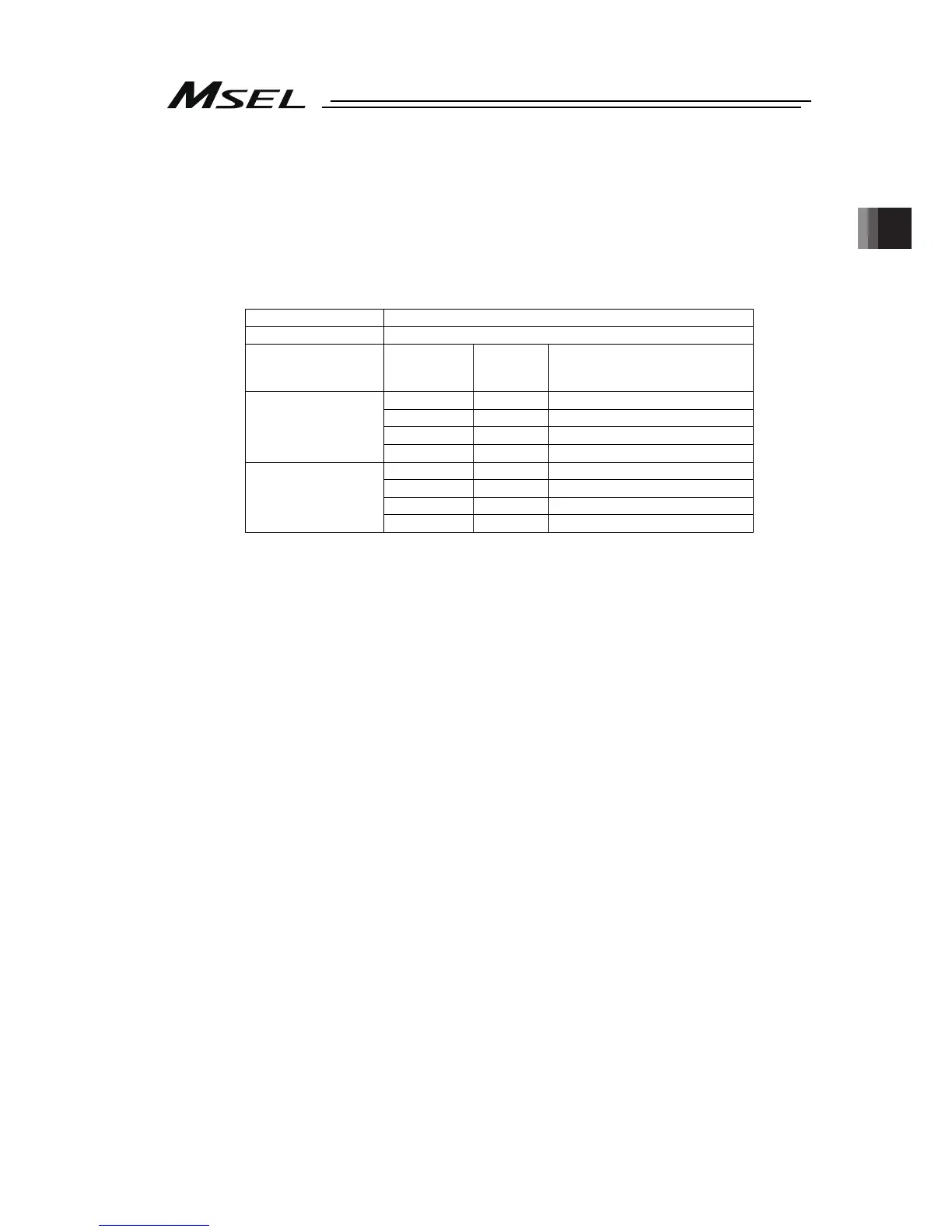
Shown below is table for the power specifications between MPO and MPI terminals.
Specifications
Voltage 24V DC (Built-in power supply)
Type PC/PCX
PCF
Numbers in brackets ( ) are in
case of high-thrust axis
1-axis type 2A 1.5A
2-axis type 4A 3.5A (3.0A)
3-axis type 6A 5.5A (5.0A)
Rated current
4-axis type 8A 7.5A (7.0A)
1-axis type 4A 6A
2-axis type 8A 10A (12A)
3-axis type 12A 14A (16A)
Maximum current
4-axis type 16A 18A (20A)
Note 4: The ratings for the emergency stop signal (EMGIN) that turns ON/OFF at the contact
CR1 and the enable signal (ENBIN) that turns on/off at the contact CR2 are 24V DC
and 10mA or less.
The emergency stop output (EMGOUT) and the enable output (ENBOUT) are
available for connection to 30V DC and 0.5A or less.
Note 5: For CR1 and CR2, select the one with coil current 0.1A or less.

 Loading...


