Chapter 5 I/O Parameter
121
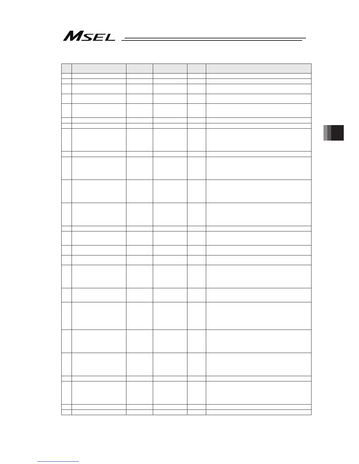
Axis-Specific Parameters
No. Parameter name
Default value
(Reference)
Input range Unit Remarks
40 System reservation 0 0 ~ 1
41 System reservation 25 0 ~ 100 DRVVR
42
System reservation
(Change prohibited)
800 0 ~ 99999999
43
System reservation
(Change prohibited)
0 -7 ~ 7
44
Length measurement
correction
0
-99999999~
99999999
0.001mm/
1M
Valid only for linear movement axes.
(Coordinates other than the encoder reference Z point will
change proportionally.)
45 (For extension) 0
46 (For extension) 0
47 Screw lead
6000
(PC/PG/
PCF/PGF)
6545
(PCX/PGX)
-1 ~ 99999999 0.001mm Valid only for linear movement axes.
48 (For extension) 0
49
Duration of absolute battery
remaining
(For PC/PG/PCF/PGF type)
2
(PC/PG/
PCF/PGF)
2, 2, 2, 2
(PCX/PGX)
0 ~ 5
* PCX/PGX is system reservation
0: 20 days
1: 15 days
2: 10 days
3: 5 days
50
Gear ratio numerator
(For PC/PG/PCF/PGF type)
1
(PC/PG/
PCF/PGF)
1, 1, 1, 1
(PCX/PGX)
1 ~ 99999999 * PCX/PGX is system reservation (Change prohibited)
51
Gear ratio denominator
(For PC/PG/PCF/PGF type)
1
(PC/PG/
PCF/PGF)
21, 21, 1, 4
(PCX/PGX)
1 ~ 99999999 * PCX/PGX is system reservation (Change prohibited)
52 (For extension) 0
53
Setting bit pattern 1 of each
axis
0H 0H ~ FFFFFFFFH
Bits 0 to 3: System reservation
Bits 4 to 7: Select complete stop position tuning feature
(0: Disable, 1: Enable)
54
Travel distance for push stop
detection at home return
20 1 ~ 99999 0.001mm Used to confirm pusing action at the time of home return.
55
Travel distance for push stop
detection at positioning
30 1 ~ 99999 0.001mm
Used to confirm pusing action according to the PUSH
command.
56
Push-abort deviation ratio at
home return
2000
(PC/PG/
PCF/PGF)
5000
(PCX/PGX)
1 ~ 99999
Deviation is compared against “Steady-state deviation of
push speed + Push-speed pulse speed × Abort deviation
ratio.
57
Push-abort deviation ratio at
positioning
5000 1 ~ 99999
Deviation is compared against “Steady-state deviation of
push speed + Push-speed pulse speed × Abort deviation
ratio.
58 Positioning band
100
(PC/PG/
PCF/PGF)
150, 150,
150, 150
(PCX/PGX)
1 ~ 9999
0.001mm
0.001deg
* (PCX/PGX type) For SCARA axes, set in coordinates for
each axis ([0.001deg] for 1
st
, 2
nd
and 4
th
axes, [0.001mm]
for 3
rd
axis).
59
Allowable deviation error ratio
(Maximum speed pulse ratio)
138
(PC/PG/
PCF/PGF)
85
(PCX/PGX)
1 ~ 9999
Deviation is compared against “Steady-state deviation of
maximum operating speed of each axis + Pulse speed of
maximum operating speed of each axis × Allowable
deviation error ratio.”
60
Position gain
(PC/PG/PCF/PGF type)
PSG
(PCX/PGX type)
45
(PC/PG/
PCF/PGF)
40
(PCX/PGX)
1 ~ 9999 /s
(PCX/PGX type)
*
Set to the same value on SCARA axis
*
Change prohibited on SCARA axis unless any supplier
indication
61 System reservation 0 0 ~ 500 %
62
System reservation
(PCX/PGX type)
Synchro FB gain
(PC/PG/PCF/PGF type)
0
(PCX/PGX)
77
(PC/PG/
PCF/PGF)
0 ~ 1000
* PCX/PGX is system reservation
(Main application Ver. 2.00 and “V1” or later of last digits
of the manufacturing code)
63 Stop special output range 1 0 ~ 9999 pulse Invalid if “0” is set.
64 Stop special output value 1 0 ~ 999 DRVVR

 Loading...


