Chapter 2 Wiring
60
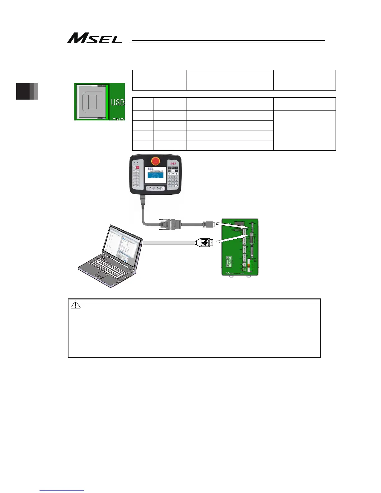
[2] USB Connector
USB Connector
Model Remarks
Controller side
UBBS-4R-D14-4D B type
Pin No.
Signal
Name
Description
Applicable Wire
Diameter
1 V
BUS
5V
2
D- Communication data -
3
D+ Communication data +
4 GND 0V
USB cable
Caution:
1)
Set “Operation Mode Setting Switch” to “MANU” side when a teaching device
is connected.
2)
Turn the power OFF before disconnecting a teaching pendant.
3
USB connector and SIO connector cannot be used at the same time. USB
connector is prioritized.
4)
When using a USB connector in MANU Mode, apply the dummy plug
(DP-4S) or connect the cable enclosed to the PC software to the SIO
connector as the enable signal detection activates.
Front view of
connector on
controller side
* SIO and USB cannot be connected at the same time.

 Loading...


