Byte Mode
The printer and host send data to each other along eight data lines (one bit per
line).
If bidirectional communication is supported by the printer and the host, the host
will take control of the data transfer.
The Negotiation Phase
The negotiation phase determines which operating mode will be used. At this time,
the host and the printer will sense what devices are attached, the supported signals
available, and which mode to use. The selected mode, in turn, defines the pins on
the 1284 connector.
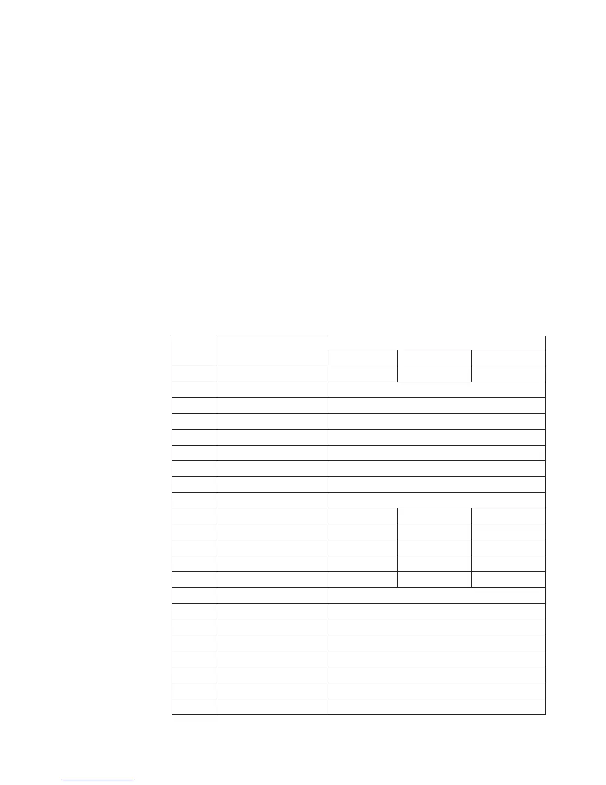
There are 36 pins on the parallel interface. Each one sends a different signal. Pin 1,
for example, can send a Strobe signal or a HostC1k signal, depending on the mode
selected. See Table 8 for the different connector signals.
Signals
Table 8 lists each of the signals associated with the corresponding pins on the 1284
interface. Descriptions of the signals follow.
Table 8. 1284 Signals
Pin Source of Data
Type of Mode
Compatible Nibble Byte
1 Host nStrobe HostClk Host/Clk
2 Host/Printer Data 1 (LSB)
3 Host/Printer Data 2
4 Host/Printer Data 3
5 Host/Printer Data 4
6 Host/Printer Data 5
7 Host/Printer Data 6
8 Host/Printer Data 7
9 Host/Printer Data 8 (MSB)
10 Printer nAck PtrClk PtrClk
11 Printer Busy PtrBusy PtrBusy
12 Printer PError AckDataReq AckDataReq
13 Printer Select Xflag Xflag
14 Host nAutoFd Host Busy HostAck
15 Not Defined
16 Logic Grid
17 Chassis Grid
18 Printer Peripheral Logic High
19 Signal Ground (nStrobe)
20 Signal Ground (Data 1)
21 Signal Ground (Data 2)
22 Signal Ground (Data 3)
Chapter 5. Printer Interfaces 215