Note: These tapped holes allow for M3 screws. The M3 mounting screw
should extend into the unit a minimum of 8 mm, and a maximum
of 11 mm.
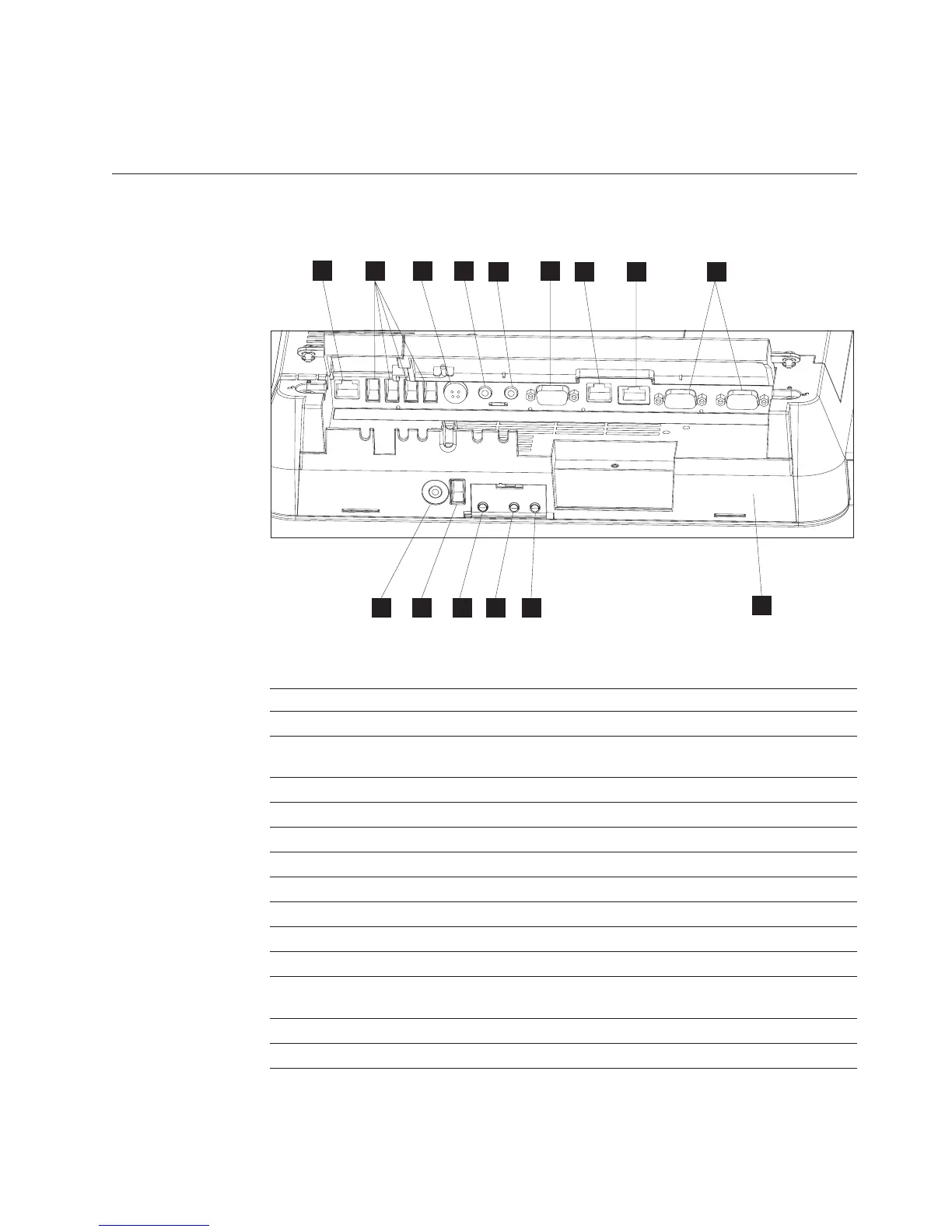
Connectors
Figure 4 shows the AnyPlace Kiosk connectors.
Table 6. Connector location
A MSR
B USB ports (4X)
C Power input connector (used by either the AC adapter
or the AnyPlace POS Hub.)
D Microphone
E Headphone
F VGA output
G Scanner
H Ethernet
I RS 232 connectors (2X)
J Headphone
K USB port
L Power button: Green indicates power and amber
indicates a hardware fault.
M N LCD brightness control buttons: minus - and plus +
O Bottom cover
B
K
A
DC
E
F
G
H
I
O
J L
M
N
Figure 4. AnyPlace Kiosk connectors
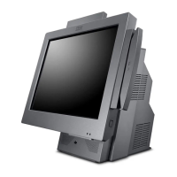
Installing the IBM AnyPlace Kiosk
Chapter 2. Installing the IBM AnyPlace Kiosk 11